EasyManua.ls Logo

AutoLoc KL800 - User Manual

Default Icon
2 pages
Print Icon
To Next Page IconTo Next Page
Loading...
GREEN/BLACK (CH3 – 500 mA)
GRAY (STARTER/IGNTION KILL OUTPUT)
GREEN/WHITE (UNLOCK – 500 mA)
BLUE/WHITE (LOCK – 500 mA)
BROWN/BLACK (CH1 – 500 mA)
YELLOW/BLACK (CH2 – 500 mA)
YELLOW (KEY ON ACCESSORY)
PURPLE/BLACK (CH4 – 500 mA)
ORANGE (PARKING LIGHTS)
+
+
KL800 3/09/04 1/2
KL800
3/09/04 2/2
KL800
USER GUIDE
WIRING DIAGRAM
8 channel system
1st channel output
LOCK
UNLOCK
2nd channel output
3rd channel output
4th channel output
Anytime
3
Anytime4
Anytime1+3
5th channel output Anytime1+2
Anytime2+4
6th channel output Anytime3+4
CODE LEARNING
a. Turn key to ON position (yellow ACC wire must be hooked up), press
valet button for 3 seconds. The parking lights will flash once to indicate
code learning mode. Press any button in order to learn the desired
remote. The parking lights will flash once for confirmation, after each
remote transmitter is learned. Up to 4 remote transmitters can be learned
at this time.
b. Turn key to OFF position or wait for 5 seconds and system will exit
code learning.
REMOTE DOOR LOCKING
a. Press button 1. The parking lights will flash once. The starter/ignition
kill circuit will be enabled and the lock output will pulse for 1 second or
until button 1 is released.
b. LED will begin flashing slowly.
REMOTE DOOR UNLOCKING
a. Press button 2. The parking lights will flash twice. The starter/ignition
kill circuit will be disabled and the unlock output will pulse for 1 second
or until button 2 is released.
b. LED will be off.
CH1 OUTPUT
Press button 3 to output channel 1 continuously until button 3 is released.
CH2 OUTPUT
Press button 4 to output channel 2 continuously until button 4 is released.
CH3 OUTPUT
Press button 1+3 to output channel 3 continuously until button 1+3 is
released.
CH4 OUTPUT
Press button 2+4 to output channel 4 continuously until button 2+4 is
released.
CH5 OUTPUT
Press buttons 1+2 to output channel 5 continuously until buttons 1+2 are
released.
CH6 OUTPUT
Press buttons 3+4 to output channel 6 continuously until buttons 3+4 are
released.
VALET SWITCH
WHITE/BLACK (CH6 - 500mA)
RED/BLACK (CH5 - 500mA)
KL800
KL800
KL800
KL800
1ST - 6TH CHANNEL
KL800
Question and Answer IconNeed help?

Do you have a question about the AutoLoc KL800 and is the answer not in the manual?

Summary

User Guide

Code Learning

Procedure to enter code learning mode using the valet button and program remotes.

Remote Door Locking

Instructions for locking doors using button 1, including starter/ignition kill activation.

Remote Door Unlocking

Instructions for unlocking doors using button 2, including starter/ignition kill deactivation.

Channel Outputs

Details on activating various auxiliary channels (CH1-CH6) using specific button combinations.

Wiring Diagrams Overview

Starter;Ignition Kill Wiring

Diagram and component connections for the starter/ignition kill circuit.

Parking Lights Wiring

Diagram for connecting the parking lights output to a relay.

Trunk;Shaved Door Handle Trigger

Wiring diagram for a trunk release or shaved door handle trigger.

Door Lock Wiring Diagrams

Negative System Door Lock Wiring

Instructions for connecting to a negative trigger door lock system.

Positive System Door Lock Wiring

Instructions for connecting to a positive trigger door lock system.

Reverse Polarity System Door Lock Wiring

Instructions for connecting to a reverse polarity door lock system.

Overview

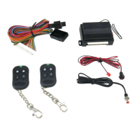
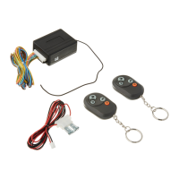
The AutoLoc KL800 is an 8-channel keyless entry system designed for automotive applications, offering remote control over various vehicle functions including door locking, unlocking, starter/ignition kill, and auxiliary outputs.

Function Description:

The primary function of the KL800 is to provide remote keyless entry and control. It utilizes a remote transmitter with four distinct buttons (Button 1, Button 2, Button 3, Button 4) and several button combinations to activate its 8 channels.

  • Remote Door Locking (Button 1): Pressing Button 1 enables the starter/ignition kill circuit and locks the doors. The parking lights will flash once, and the lock output will pulse for 1 second or until Button 1 is released. The LED on the unit will begin flashing slowly, indicating the system is armed.
  • Remote Door Unlocking (Button 2): Pressing Button 2 disables the starter/ignition kill circuit and unlocks the doors. The parking lights will flash twice, and the unlock output will pulse for 1 second or until Button 2 is released. The LED will turn off, indicating the system is disarmed.
  • Starter/Ignition Kill: This security feature prevents the vehicle from starting. It is enabled when the doors are locked (Button 1) and disabled when the doors are unlocked (Button 2).
  • Auxiliary Channel Outputs: The system provides six auxiliary outputs (CH1-CH6) that can be used to control various other vehicle accessories. These outputs are continuous as long as the corresponding button or button combination is held down.
    • CH1 Output (Button 3): Activates the 1st channel output.
    • CH2 Output (Button 4): Activates the 2nd channel output.
    • CH3 Output (Button 1+3): Activates the 3rd channel output.
    • CH4 Output (Button 2+4): Activates the 4th channel output.
    • CH5 Output (Button 1+2): Activates the 5th channel output.
    • CH6 Output (Button 3+4): Activates the 6th channel output.
  • Trunk/Shaved Door Handle Trigger: The system can be wired to trigger a trunk release or shaved door handle mechanism. This typically involves connecting one of the auxiliary channels (1st-6th channel) to a relay that controls the release mechanism. The trigger output is positive.
  • Parking Lights Control: The system can flash the vehicle's parking lights to provide visual confirmation of lock/unlock commands and during code learning. It supports both positive and negative parking light trigger systems, requiring a relay for negative trigger setups.

Important Technical Specifications:

  • Channels: 8 channels (2 for lock/unlock/kill, 6 auxiliary).
  • Auxiliary Output Current: CH1-CH6 outputs are rated at 500mA each (Brown/Black, Yellow/Black, Green/Black, Purple/Black, Red/Black, White/Black wires respectively).
  • Power Input: The system operates on a +12V DC power supply, typically from the vehicle's battery (Red wire). A chassis ground connection is also required (Black wire).
  • Accessory Power: Requires a connection to the vehicle's accessory power (Yellow wire) for code learning.
  • Parking Light Output: Orange wire.
  • Starter/Ignition Kill Output: Gray wire.
  • Lock Output: Blue/White wire (500mA).
  • Unlock Output: Green/White wire (500mA).
  • Fuse: A 2A fuse is recommended for the +12V power input.
  • Relay for Starter/Ignition Kill: The starter/ignition kill function utilizes a standard 5-pin automotive relay (e.g., Bosch type) to interrupt the ignition switch circuit. The KL800's Gray wire connects to terminal 85 of this relay.
  • Relays for Door Locks: Depending on the vehicle's door lock system (negative, positive, or reverse polarity), additional relays may be required for the lock/unlock functions. The manual provides detailed wiring diagrams for these scenarios.

Usage Features:

  • Code Learning: The system allows up to 4 remote transmitters to be learned.
    1. Turn the ignition key to the ON position (yellow ACC wire must be connected).
    2. Press the valet button for 3 seconds. The parking lights will flash once, indicating code learning mode.
    3. Press any button on the desired remote transmitter. The parking lights will flash once for confirmation after each remote is learned.
    4. Turn the ignition key to the OFF position or wait for 5 seconds to exit code learning mode.
  • Valet Switch: A valet switch is included for code learning and potentially other system functions (though only code learning is explicitly mentioned in the provided text).
  • Visual Confirmation: Parking lights flash once for lock/arm and twice for unlock/disarm, providing clear visual feedback.
  • LED Indicator: An LED on the unit flashes slowly when the system is armed (doors locked, kill enabled) and is off when disarmed.

Maintenance Features:

  • Professional Installation Recommended: The manual strongly recommends installation by qualified automotive professionals due to the complexity of vehicle wiring and the potential for property damage or personal injury if improperly installed.
  • Troubleshooting (Implicit): The detailed wiring diagrams for various door lock systems (negative, positive, reverse polarity) and parking light configurations serve as a guide for installers to correctly integrate the KL800 into different vehicles, implicitly aiding in troubleshooting installation issues.
  • Fuse Protection: The 2A fuse on the main power input protects the system from overcurrent, which is a standard maintenance and safety feature.
  • Relay-Based Design: The use of external relays for high-current applications like starter kill and door locks means that if a high-current component fails, only the inexpensive relay needs to be replaced, rather than the main control unit.

The AutoLoc KL800 provides a comprehensive and flexible solution for adding remote keyless entry and auxiliary control to a vehicle, emphasizing security through its starter/ignition kill feature and adaptability to various vehicle wiring configurations.

AutoLoc KL800 Specifications

General IconGeneral
BrandAutoLoc
ModelKL800
CategoryRemote Starter
LanguageEnglish

Related product manuals