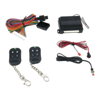
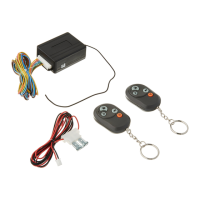
KEYLESS ENTRY SYSTEM
5 channel system
USER GUIDE
USER GUIDE AND INSTALLATION MANUAL
INTRODUCTION
CODE LEARNING
a. Turn key to ON position, press valet button for 3 seconds. The parking
lights will flash once to indicate code learning mode. Press any button in
order to learn the desired remote. The parking lights and LED will flash
once for confirmation, after each remote transmitter is learned. Up to 4
remote transmitters can be learned at this time.
b. Turn key to OFF position or wait for 5 seconds and system will exit
code learning.
REMOTE DOOR LOCKING
a. Press button 1. The parking lights will flash once. The starter/ignition
kill circuit will be enabled and the lock output will pulse for 1 second or
until button 1 is released.
b. LED will begin flashing slowly.
REMOTE DOOR UNLOCKING
a. Press button 2. The parking lights will flash twice. The starter/ignition
kill circuit will be disabled and the unlock output will pulse for 1 second
or until button 2 is released.
b. LED will be off.
CH1 OUTPUT
Press button 1 to output channel 1 continuously until button 1 is released.
CH2 OUTPUT
Press button 2 to output channel 2 continuously until button 2 is released.
CH3 OUTPUT
Press button 3 to output channel 3 continuously until button 3 is released.
CH4 OUTPUT
Press button 4 to output channel 4 continuously until button 4 is released.
CH5 OUTPUT
Press buttons 1+3 to output channel 5 continuously until buttons 1+3
are released.
ABOUT YOUR DOOR LOCKING SYSTEM
All power door locking systems have switches to activate doors. These
switches are usually located on the door or center console. In some cases
(BMW) the switch is located inside the drivers door actuator. Your door
lock switch will have at least 2 trigger wires, one for locking your doors
called the LOCK wire, and one for unlocking your doors called the
UNLOCK wire. Your switch will also have one sender wire. When the
sender wire connects to a trigger wire your doors will activate (unlock or
lock).
When you push your door lock switch to "lock", your sender wire
connects with your lock wire, to lock your doors. When you push your
door lock switch to "unlock", your sender wire connects with your unlock
wire, to unlock your doors.
Negative and Positive triggers are the two main types of door locking
systems. On a negative trigger system your sender wire is "-". When you
give a "-" to the trigger wires they will activate your doors (unlock or
lock). On a positive trigger system your sender wire is "+". When you
give a "+" to the trigger wires they will activate your doors (unlock or
lock).
LOCATION OF WIRES
1. Open the Door
2. Locate the Power Door Lock Switch.
3. Remove the switch from the door so that you can gain access to the
wires
Note: If your car has no door lock switch then you have central locking
(BMW). Central locking systems have the unlock, lock, and sender wires
built in to the drivers side door actuator (inside door). There is no need to
remove the driver's door panel since these wires travel from the driver's
door, through the door jam, to the interior of your vehicle. Test all wires
coming from the drivers door for the lock, unlock, and sender wires.
Wire according to the proper system.
©2002 The Hoffman Group L.L.C. All rights reserved. All information on these pages are for reference only. THG LLC is not responsible for any inaccuracies. THG LLC is also not responsible for any property
damage or personal injuries resulting from the use of the information. Installation by qualified automotive professionals is highly recommended.
Button 1 Button 2
Button 3 Button 4
Preprogrammed Remote Transmitter
Button Function Condition
1 Enable starter/ignition
kill and lock door
1st channel output
Starter/ignition
kill disabled
2
Disable starter/ignition
kill and unlock door
2nd channel output
Starter/ignition
kill enabled
3 3rd channel output Anytime
4 4th channel output Anytime
1+3 5th channel output Anytime
1
TECH SUPPORT: 503.693.1918 WWW.AUTOLOC.COM
REV2 4.22.03
KL550 1/4