Revised 11/19/99 • BACview
2
Hardware Guide 5 © 1999 Automated Logic Corporation
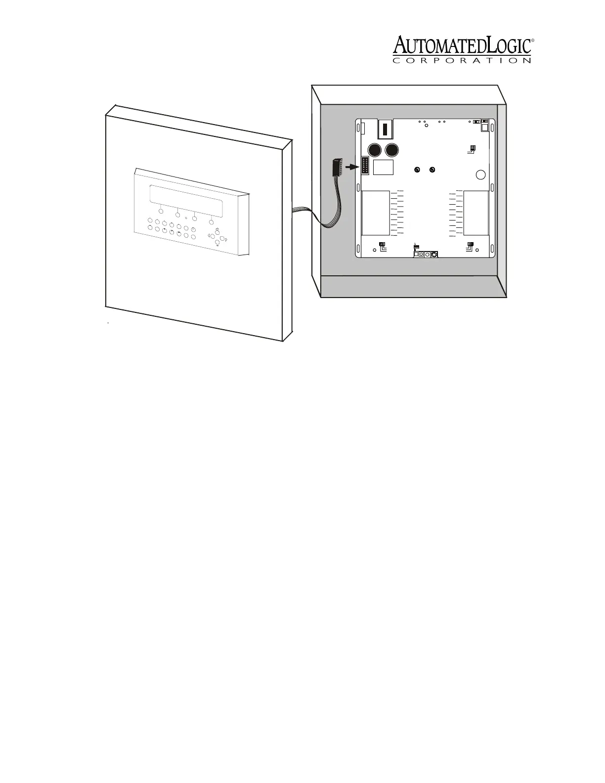
2. Plug the 14-pin TTL ribbon cable
connector into the Auxiliary Device port of
themoduletheBACview
2
will
communicate with.
3. Turn on the power to the module that the
BACview
2
will communicate with.
The BACview
2
is now properly wired. Before
the BACview
2
can be used, create, compile,
and transfer the screen file into the module.
Refer to the BACview
2
Programmer's Guide
and the BACview Programmer’s Tutorial for
more information.
Protection
The BACview
2
module is protected by an
internal Polyswitch on the incoming power.
This Polyswitch is not replaceable and will
reset itself if the condition that caused the
fault returns to normal.
Figure 4. Type II Mounting
Type: 0320
Cat.#
MODULE
I/O
Expans ion
A - Input Signal
B - Gnd/Loop
Power
I/O
Expans ion
A
B
A
B
A
B
A
B
A
B
A
B
A
B
A
B
IN1
IN2
IN3
IN4
IN5
IN6
IN7
IN8
IN 9
IN 10
IN 11
IN 12
IN 13
IN 14
IN 15
IN 16
IN 24
IN 23
IN 22
IN 21
IN 20
IN 19
IN 18
IN 17
B
A
B
A
B
A
B
A
B
A
B
A
B
A
B
A
IN 32
IN 31
IN 30
IN 29
IN 28
IN 27
IN 26
IN 25
B
A
B
A
B
A
B
A
B
A
B
A
B
A
B
A
0-
20mA0-
5Vdc
Thermistor
/
dr y con-
tact
On
Off
Gnd
24 Vac
Class2
24 Vac,50-60
Hz
35 VA, 1.5A
Use Copper
Co nd uct ors O nly
A
B
A
B
A
B
A
B
A
B
A
B
A
B
A
B
Run Error
Control Module
Pow er
Access
Port
Rx
Net
+
Net
-
Optional
S hield
Format
Tx
Auxilary
Device
Port
CM net
Universal Input
1-16
Mode Select
0-
20 mA0-5 Vd c
Thermistor/
dry contact
U nivers al Inp ut
17 -32
Mode Select
Module
Address
0
5
1
4
2
3
9
6
8
7
10's 1's
Arc 156
R
LIST ED
88FO
OpenEnergy
Ma nagem entE quipme nt
R
LIST ED
88FO
C
CM net M ode
UseSingleClass2
Source O nly
9600/38.4k
 Loading...