Technical Specifications FHCRX-1V2 and FHCRX-2V2 FHRX-2V2
Power supply 12V - 24V AC or DC 9V - 24V DC ONLY
Frequency Multi Frequency Multi Frequency
Memory Capacity 250 Transmitters 250 Transmitters
Programmable Modes: Pulse, Hold, Timer*
Controlling Outputs FHCRX-1V2 1 x Common
1 x Normally Open
1 x Normally Closed
FHCRX-2V2 2 x Common
2 x Normally Open
2 x Normally Closed
Output 1:
Open collector output at pin one for channel
one (40 dc volts 100 ma max)
Output 2:
Open collector output at pin four for channel
two (40 dc volts 100ma max)
Relay Contact Rating 1 amp @ 24 volts DC N/A
Antenna Wire Length** 170mm 170mm
*Timer mode available with ATA’s Universal Programmer.
** An optional co-axial antenna is available for use with the receiver in difficult reception areas. The antenna has to be mounted as high as
possible so that it is not obstructed, e.g. on top of a fence, or on a wall at the front of a garage, etc. Connect the core of co-axial lead to replace
the existing antenna wire (inner screw socket). Connect shield to the spare (outer) screw socket.
RED
RED BLUE
BLACKWHITE
BLUE WHITE
BLACK
5
380
NOM
26 NOM
-
ITEM
DEBUR AND BREAK SHARP EDGES
CHAMFER: 0.5 x 45
0.XX
IS PROHIBITED.
AUTOMATIC TECHNOLOGY AUSTRALIA Pty Ltd.
SURFACE FINISH
GENERAL TOLERANCES:
0.5ANGLE:
ANY REPRODUCTION IN PART OR AS A WHOLE
georgek@ata-aust.com.au
TITLE:
********
SCALE:
PART NO.
A3
-
********
REV.
DRAWING NO.
-----
5321
A
B
SHEET
8
C
DESCRIPTION
DWG NO.
**.**.**
0.05
NAME
F
RADIUS: 0.5
7
WITHOUT THE WRITTEN PERMISSION OF
PROPRIETARY AND CONFIDENTIAL
1 : 1
REMARKSMAT'L
-----------
------
6
Automatic Technology Australia Pty Ltd.
E
D
DATE
4
-
REQ'D
DECIMAL: 0.X
0.1
THE INFORMATION CONTAINED IN THIS
DRAWING IS THE SOLE PROPERTY OF
AUTOMATIC TECHNOLOGY AUSTRALIA Pty Ltd.
6-8 FIVEWAYS BLVD, KEYSBOROUGH, 3173
PHONE: (03) 9791 0200 FAX: (03) 9791 0250
WEB: www.ata-aust.com.au
*****
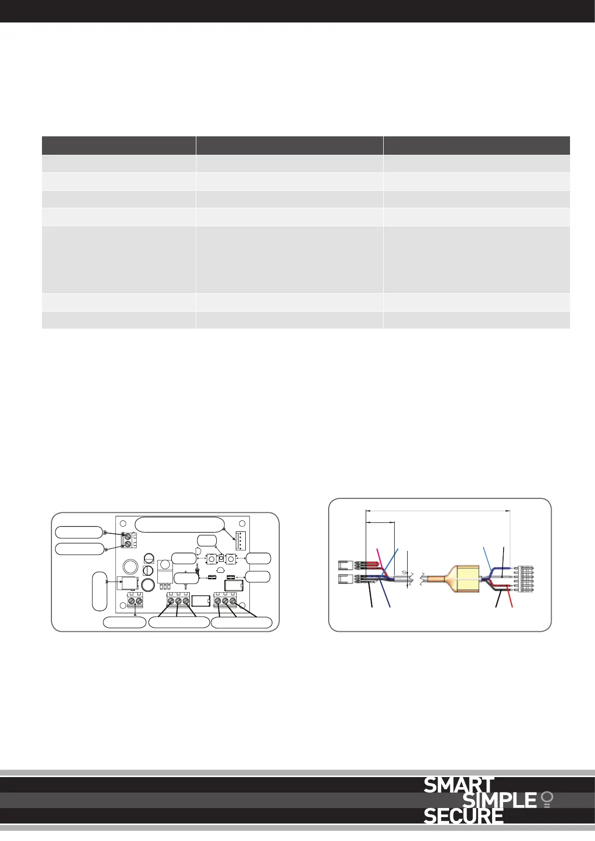
HARNESS TO USE WITH RECEIVER
ANTENNA
AC SKT
PWR SKT
NC NO COM
PG3-CONNECTOR
SW1
JP1
LED
JP2
SW2
NC NO COM
SHIELD
CO-AXIAL CONNECTION
An optional coaxial antenna is available for use with the receiver in
difficult reception areas. The antenna has to be mounted as high as
possible so that it is not obstructed, e.g. on top of a fence, or on a
wall at the front of a garage, etc. Connect the core of coaxial lead
to replace the existing antenna wire (outer screw socket). Connect
shield to the spare (inner) screw socket.
HARNESS
The harness to connect receiver to the opener can be bought from
ATA (Order code #01905). User may have to cut and strip wires to
connect to different openers. Cut and leave white wire if the second
channel is not used.
OPTIONAL EXTRAS
SPECIFICATIONS
 Loading...