Page 2
DURApulse GS20 AC Drive Quick-Start Guide – 1st Ed 06/29/2020
DURApulse GS20 AC Drive Quick-Start Guide
GS20_QSP_1ed 06/29/2020
Wiring Precautions
1) The factory default condition is +24 V/ S1/ S2 shorted by jumper, as shown in the block 1 of the figure above.
Refer to the wiring chapter of the User Manual for more details.
2) The +24 V power supply for safety function is only for STO use and cannot be used for other purposes.
3) The RELAY terminal uses the PCB terminal block:
• Tighten the wiring with a 3.5 mm width and 0.6 mm thickness slotted screwdriver.
• The ideal length of stripped wire at the connection side is 6–7 mm.
• When wiring bare wires, make sure they are perfectly arranged to go through the wiring holes.
4) The control circuit terminal uses a spring clamp terminal block:
• Tighten the wiring with a 2.5 mm width and 0.4 mm thickness slotted screwdriver.
• The ideal length of stripped wire at the connection side is 9 mm.
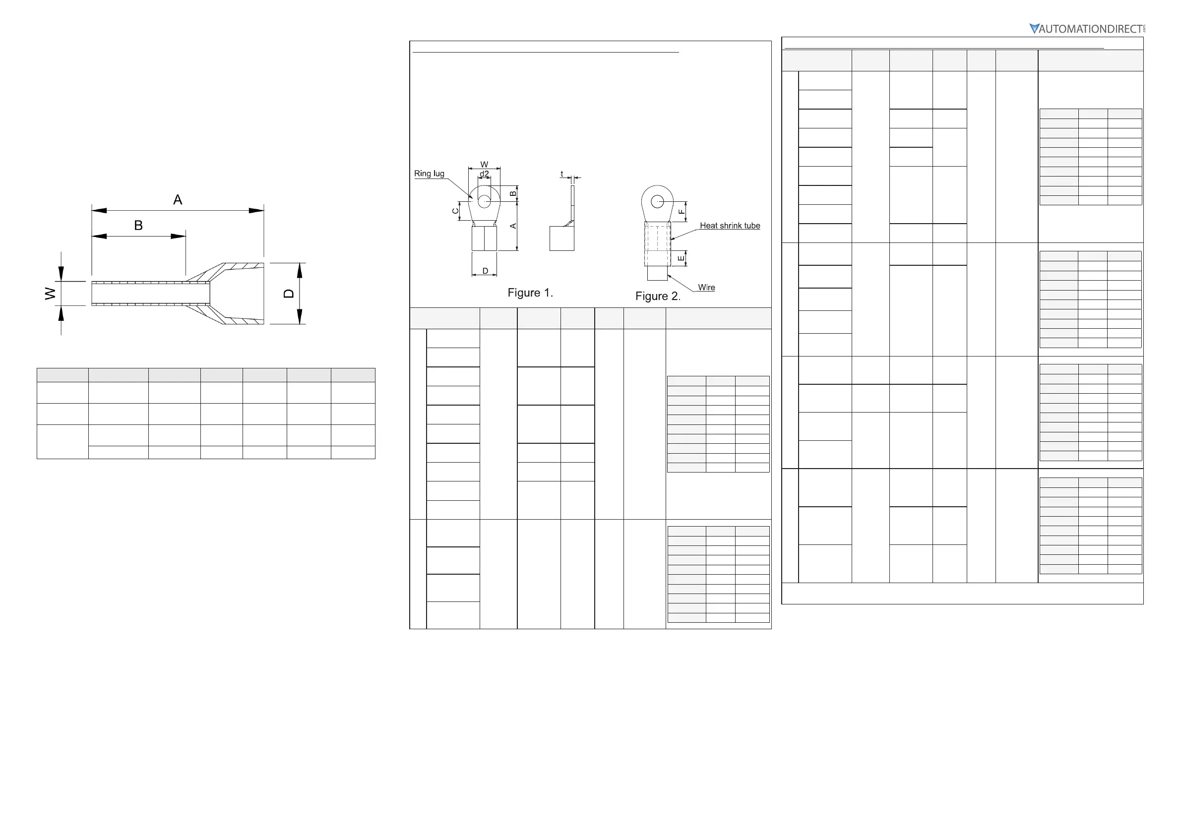
Recommended models or dimensions for ferrule terminals
Wire Gauge Manufacturer Model Name A (MAX) B (MAX) D (MAX) W (MAX)
0.25 mm2
[24 AWG]
PHOENIX
CONTACT
AI 0,25- 8 YE 12.5 8 2.6 1.1
0.34 mm2
[22 AWG]
PHOENIX
CONTACT
AI 0,34- 8 TQ 12.5 8 3.3 1.3
0.5 mm2
[20 AWG]
PHOENIX
CONTACT
AI 0,5 - 8 WH 14 8 3.5 1.4
Z+F V30AE000006 14 8 2.6 1.15
Specifications for Wiring Terminals – Main-Circuit Terminals
Notes:
• If you install at Ta 45°C above environment, please use copper wire with a 600V voltage rating and
temperature resistance of 90°C or higher.
• For UL compliant installation, you must:
1) Use 75°C temperature resistant copper wire or better. Do not reduce wire gauge when using higher
temperature wire.
2) Use the specific ring lug part listed in the table below.
3) Use crimp tool KST2000D-1322 or IZUMI 5N18 for 22–8 AWG wire, or
IZUMI 9H-60 for 6–4 AWG wire.
Drive Models
Max Wire
Gauge
Min Wire
Gauge
Ring
Lug P/N
Screw
Torque
(±10%)
Ring Lug Dimensions (mm)
Frame A
GS21-10P2
14AWG
[2.1 mm
2
]
16AWG
[1.3 mm
2
]
RNBS
2-3.7
M3.5
9 kg-cm
[7,8 lb-in.]
[0.88 N·m]
Dimension Value Min/Max
A 9.8 Max
B 3.2 Max
C 4.8 Min
D 4.1 Max
d2 3.7 Min
E 13.0 Min
F 4.2 Min
W 6.6 Max
t 0.8 Max
GS21-20P2
GS23-20P2
18AWG
[0.82 mm
2
]
RNBS
1-3.7
GS23-20P5
GS21-10P5
14AWG
[2.1 mm
2
]
RNBS
2-3.7
GS21-20P5
GS23-40P5
18AWG
[0.82 mm
2
]
RNBS
1-3.7
GS23-21P0
16AWG
[1.3 mm
2
]
RNBS
2-3.7
GS23-41P0
18AWG
[0.82 mm
2
]
RNBS
1-3.7
GS23-51P0
Frame B
GS23-22P0
12AWG
[3,3 mm
2
]
14AWG
[2.1 mm
2
]
RNBS
2-4
M4
15 kg-cm
[13,0 lb-in.]
[1.47 N·m]
Dimension Value Min/Max
A 12.1 Max
B 3.6 Max
C 6.1 Min
D 5.6 Max
d2 4.3 Min
E 13.0 Min
F 4.5 Min
W 7.2 Max
t 1 Max
GS23-42P0
GS23-52P0
GS21-21P0
Specifications for Wiring Terminals – Main-Circuit Terminals (continued)
Drive Models
Max Wire
Gauge
Min Wire
Gauge
Ring
Lug P/N
Screw
Torque
(±10%)
Ring Lug Dimensions (mm)
Frame C
GS21-11P0
8AWG
[8.4 mm
2
]
10AWG
[5.3 mm
2
]
RNBS
5-4
M4
20 kg-cm
[17,4 lb-in.]
[1.96 N·m]
Dimension Value Min/Max
A 17.8 Max
B 5.0 Max
C 6.1 Min
D 7.2 Max
d2 4.3 Min
E 13.0 Min
F 5.5 Min
W 8.0 Max
t 1.2 Max
GS21-22P0
GS21-23P0
8AWG
[8.4 mm
2
]
RNBS
8-4
GS23-23P0
12AWG
[3,3 mm
2
]
RNBS
5-4
GS23-25P0
10AWG
[5.3 mm
2
]
GS23-43P0
14AWG
[2.1 mm
2
]
RNBS
2-4
GS23-45P0
GS23-53P0
GS23-55P0
12AWG
[3,3 mm
2
]
RNBS
5-4
Frame D
GS23-27P5
8AWG
[8.4 mm
2
]
8AWG
[8.4 mm
2
]
RNBS 8-4
M4
20 kg-cm
[17,4 lb-in.]
[1.96 N·m]
Dimension Value Min/Max
A 17.8 Max
B 5.0 Max
C 6.1 Min
D 7.2 Max
d2 4.3 Min
E 13.0 Min
F 5.5 Min
W 8.0 Max
t 1.2 Max
GS23-47P5
10AWG
[5.3 mm
2
]
RNBS 5-4
GS23-4010
GS23-57P5
GS23-5010
Frame E
GS23-2010
6AWG
[13.3 mm
2
]
6AWG
[13.3 mm
2
]
RNBS
14-5
M5
25 kg-cm
[21,7 lb-in.]
[2.45 N·m]
Dimension Value Min/Max
A 27.1 Max
B 6.1 Max
C 10.5 Min
D 11.5 Max
d2 5.3 Min
E 13.0 Min
F 6.5 Min
W 12.2 Max
t 1.7 Max
GS23-2015*
4AWG
[21.2 mm
2
]
4AWG
[21.2 mm
2
]
RNBS
22-5
GS23-4015
6AWG
[13.3 mm
2
]
8AWG
[8.4 mm
2
]
RNBS 8-5
GS23-4020
Frame F
GS23-2020
2AWG
[33.6 mm
2
]
2AWG
[33.6 mm
2
]
RNBS
38-6
M6
40 kg-cm
[34,7 lb-in.]
[3.92 N·m]
Dimension Value Min/Max
A 35.0 Max
B 9.0 Max
C 13.3 Min
D 14.0 Max
d2 6.2 Min
E 13.0 Min
F 19.5 Min
W 18.0 Max
t 1.8 Max
GS23-4025
6AWG
[13.3 mm
2
]
RNBS
14-6
GS23-4030
4AWG
[21.2 mm
2
]
RNBS
22-6
* The GS23-2015 drive must be wired with a ring terminal of the specified dimensions.
 Loading...