2
Tech Support 770-844-4200www.productivity1000.com
WARNING:
Do not add or remove modules with
field power applied.
Step One: With latch
in “locked” position, align
connectors on the side of
each module and stack
by pressing together.
Click indicates lock is
engaged.
Step Three:
To unstack modules, pull
locking latch up into the unlocked position
and then pull modules apart.
Step Two: Attach field wiring using
the removable terminal block or ZIPLink
wiring system.
WIRE STRIP
LENGTH
MIN
MAX
P1-08TD1
Check all latches are
secure after modules
are connected.
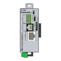
P1-540
RUN
STOP
PWR
RUN
CPU
REMOTE I/O
RS-232 RS-485
10/100
ETHERNET
ACT LINK
G
-
+
T
LINK ACT
PGM
LINK
RXTXTXRTSRX
USB
µSD
™
External Power
- 24VDC
Micro USB 2.0 (Type B)
- Programming
- Online monitoring
- Firmware/Debug
RS-485 Serial Port
- Modbus/ASCII
(master peripheral device
or multiple slave devices)
using the same protocol
RS-232 Serial Port (RJ12)
- Modbus/ASCII
(master or slave)
peripheral device
CPU Status Indicators
microSD Port
- removable flash memory
10/100 MB
Ethernet Port
- Programming
- Online monitoring
- Email (SMTP client)
- Ethernet IP Client
and Server
- Modbus TCP Client
and Server
- Custom Protocol
over Ethernet
- ProNet
 Loading...