2
www.AutomationDirect.com
1-800-633-0405
Copyright 2023, AutomationDirect.com Incorporated/All Rights Reserved Worldwide
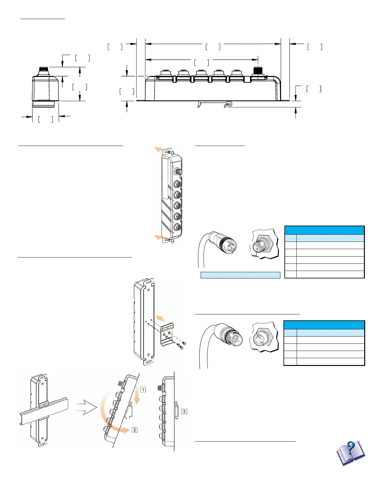
Dimensions:
mm [inches]
8.8
0.35
35.0
1.38
158.9
6.26
191.2
7.53
12.3
0.48
12.3
0.48
47.8
1.88
12.8
0.50
37.2
1.46
215.8
8.50
30.0
1.18
44.6
1.76
25.0
0.98
16.1
0.64
25.0
0.98
2X
10.0
0.39
2X
5.0
0.20
203.8
8.02
25.0
0.98
4X
R2.5
0.10
8/14/2023
STRIDE INDUSTRIAL UNMANAGED ETHERNET SWITCH, 5 PORTS, (5) ETHERNET 10/100Base-T
(M12) PORTS(S), -40 to +75 DEG C, PLASTIC HOUSING, IP67, 35mm DIN RAIL OR PANEL MOUNT
mm
[inch]
UNLESS OTHERWISE
SPECIFIED UNITS ARE:
LATEST VERSION
PART DIMENSIONS MAY DIFFER SLIGHTLY
DUE TO MANUFACTURER'S VARIANCES
NOT TO
SCALE
3rd
ANGLE
SE3-SW5U-N67-T
SHEET 1 OF 1
INCH UNITS USED FOR
PART DESIGN
1-800-633-0405
AutomationDirect.com
Unit weight: 0.4 kg [0.88 lb]
Installation – DIN Rail Mounting:
Using the included DIN rail mounting bracket, the switch
can be snapped onto a standard 35 x 7.5 mm height DIN rail
(Standard: CENELEC EN50022)
To install the DIN rail mounting bracket, use
the included screws as shown in the figure
to the right.
After the DIN-Rail bracket is installed on the
rear of the switch, follow the steps below to
mount the switch:
1. Hook top back of unit over the DIN rail.
2. Push bottom back onto the DIN rail until
it snaps into place.
3. Check to ensure that the bracket is
mounted tightly to the rail.
To remove the switch from the DIN rail, push the unit down to free the
bracket from the bottom of the DIN rail, then reverse the above steps.
Panel mounting steps:
1. Prepare 2 screws for mounting the switch to a wall.
(M3 or M4 screws are recommended.)
2. Locate two screw holes in the wall or panel based
on the positions of two screw holes on the mount-
ing brackets.
3. Insert the screws through the screw holes on the
switch and secure the switch to the panel.
Installation – Panel Mounting:
The switch is designed to be panel mounted vertically
or horizontally using the steps below.
Power Wiring:
The switch can be powered from the same DC source that is used to power
your other devices. To maintain the UL listing, this source must be a Class 2
power supply. A DC voltage in the range of 12–48 VDC needs to be applied
through an M12 connector as shown in the chart below. We recommend
grounding the switch to the panel or chassis ground using an M3 or M4 ground
screw and grounding wire, attached to either the top or bottom wall mounting
hole. To reduce down time resulting from power loss, the switch can be
powered redundantly with a second power supply as shown in the chart below.
A recommended DC power supply is AutomationDirect.com part number
PSL-24-030.
Communication Ports Wiring:
Communication Port Pin Definitions
Pin MDI Signal
1 Transmit Data + (TD+)
2 Receive Data + (RD+)
3 Transmit Data - (TD-)
4 Receive Data - (RD-)
1
2
43
1
2
4
3
Power Port Pin Definitions
Pin Description
1 Power Input 1 +
2 Power Input 2 +
3 Power Input 2 -
4 Power Input 1 -
5 Ground
1
2
4
3
1
2
3
4
5
5
Recommended Wire Size 24 – 18 AWG
Additional Help and Support
• For additional product support, specifications, and
installation, download User Manual SE3-USER-M from the
Product Manuals area of www.AutomationDirect.com.
• For additional technical support and questions, call our
Technical Support team @ 770-844-4200.
 Loading...