17
16
8
94
5
6
7
10
2
1
3
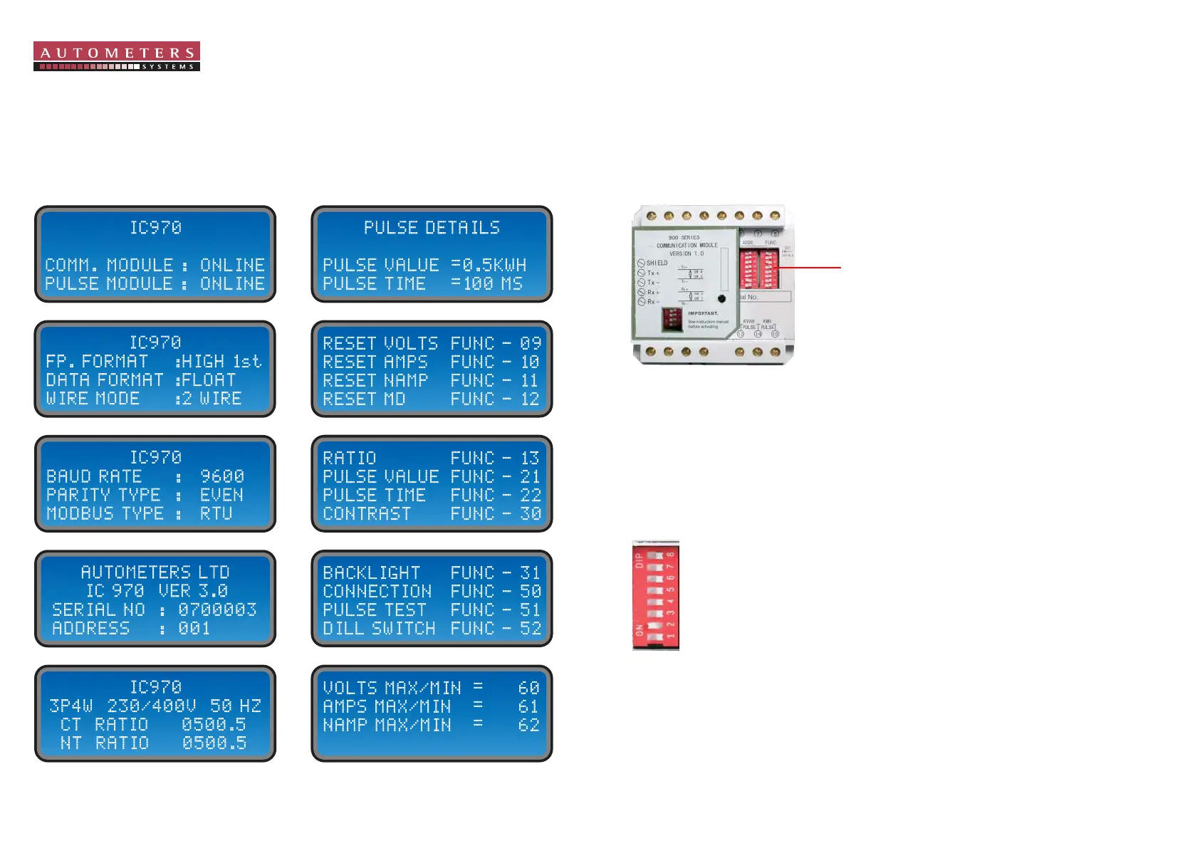
When you press the information key and the communication module is fitted the following displays
will appear.
To move on to the displays shown below press the “INFORM” key repeatedly until
the required display is shown.
Please Note.
If there is no communication module fitted, you will only see displays 1, 4, 5, 6, 7, 8, 9 & 10.
You will notice in the picture below two red vertical rows of switches 1 - 8. Above each row the
letters “ADDR” and “FUNC” are printed. These individual switches will have to be selected to
programme the correct protocol in the meter. See below.
You will notice two red binary switches next to each other, one is marked “ADDR” and the other
switch is marked “FUNC”.
The binary switch has 8 switches numbered 1-8.
The number sequence is as follow.
1 = 1 3= 4 5= 16 7 = 64
2= 2 4= 8 6= 32 8 = 128
“ADDR” Binary Switch
The binary switch on the left is marked “ADDR” and is for setting the meters address number.
Each meter in the Modbus system must have its own unique number.
E.G. by moving the number 1 switch to the “on" position you have numbered this meter as 1.
By switching numbers 1 and 4 to the “on” position this becomes number 9.
The highest number which you can allocate to a meter is 128.
Binary Switches
ADDR.
Information key
Programming the communication module