Do you have a question about the Autonics AT11DN and is the answer not in the manual?
Highlights potential injury or damage from improper use or product damage.
Covers risks when using with machinery, electrical connections, and modifications.
Details model codes (DN, EN) and socket types for ordering.
Provides physical measurements and panel cut-out dimensions for installation.
Covers model details, power, input/output specs, and accuracy parameters.
Details operating conditions, vibration, shock, life cycle, and environmental ratings.
Illustrates terminal connections for the AT11DN model.
Illustrates terminal connections for the AT11EN model.
Describes the ON Delay mode with its time chart and input signals.
Details the Flicker mode (OFF start) with its timing and signal requirements.
Explains the Flicker 1 mode (ON start) and its operational timing.
Covers the OFF Delay mode, including timing and signal configurations.
Details the ON/OFF Delay mode with its time chart and signal inputs.
Explains the Interval mode and its operational timing characteristics.
Guidance on using gold-plated switches for reliable contact input.
Specifies transistor characteristics for NPN open collector inputs.
Recommends a minimum signal width of 50ms for various inputs.
Explains the design without a transformer and the use of isolation transformers.
Advises using terminal 2 as common to prevent damage.
Warns against parallel wiring of input signals with power lines.
Recommends changing settings only when the unit is powered off.
Lists unsuitable locations and environmental conditions for operation.
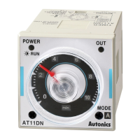
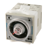
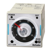
The Autonics AT11DN/AT11EN is an analog timer designed for precise control in various industrial applications. This device is engineered for panel mounting and offers a range of timing functions, making it suitable for a wide array of machinery and systems.
The AT11DN/AT11EN timer operates as a time-limit relay, providing either two time-limit contacts (DN model) or one time-limit contact and one instantaneous contact (EN model). It supports a broad control time setting range, from as short as 0.05 seconds to as long as 100 hours, allowing for highly flexible timing configurations. The timer features a clear front panel with a time range selector and a time unit display (seconds, minutes, hours, or 10-hour increments), enabling users to easily set and monitor the desired timing parameters. An operation/power LED indicates the timer's status, flickering during operation and turning off when the timer stops. An output LED provides visual feedback on the relay output status.
The device offers multiple operation modes to suit different control requirements. These include:
Input signals for START, RESET, and INHIBIT functions can be provided via relay contacts or NPN open collector transistors. The INHIBIT function allows for pausing the time progression, which resumes once the INHIBIT signal is removed. The RESET function immediately resets the timer, stopping any ongoing time progression and returning the output to its initial state.
The AT11DN/AT11EN is designed for ease of use and reliability. Its analog dial and clear indicators on the front panel simplify the process of setting time ranges and monitoring operation. The timer is compatible with both AC and DC power supplies, offering versatility in integration into existing systems. For DC power inputs, users are advised to carefully check the polarity before connection to prevent damage.
When connecting input signals, it is recommended to use gold-plated switches with good contact assurance and short bounding times for relay contact inputs to ensure reliable operation. For NPN open collector transistor inputs, specific transistor characteristics are recommended to maintain optimal performance. Signal widths for START, RESET, and INHIBIT inputs should be maintained at a minimum of 50ms for both relay contact and solid-state inputs.
The timer's design incorporates safeguards against common issues. It is built without a transformer in its power circuit, with the sensor power supplied by an isolation transformer that is not grounded on the secondary side. This design consideration helps prevent potential damage. Proper wiring practices are crucial, especially when connecting multiple timers to a single input signal, to avoid short-circuit currents and ensure system integrity.
Users should avoid changing the setting time, time range, or operation mode while the unit is operating, as this may cause malfunctions. It is recommended to make such adjustments after the power has been cut off. The device is intended for indoor use and should not be exposed to severe vibration, impact, strong alkalis or acids, direct sunlight, or strong magnetic fields/electric noise, as these conditions can affect its performance and lifespan.
To ensure the longevity and reliable operation of the AT11DN/AT11EN timer, certain maintenance guidelines should be followed. When cleaning the unit, only use a dry cloth; water or organic solvents should be avoided as they can cause electric shock, fire, or damage to the product. It is important to prevent dust or wire dregs from entering the unit, as this can lead to mechanical trouble or fire.
The timer is designed for continuous operation, but prolonged use without proper environmental conditions may shorten its lifespan due to heat generated by internal electric components. Therefore, ensuring the operating environment adheres to the specified temperature and humidity ranges is important.
For testing dielectric voltage and insulation resistance of the control panel where the unit is installed, it is advised to isolate the timer from the control panel circuit or short-circuit all its terminals to prevent damage. In cases where the timer is used with critical machinery (such as nuclear power control, medical equipment, or safety devices), installing fail-safe mechanisms is highly recommended, and Autonics should be contacted for specific guidance. Any disassembly or modification of the unit should only be performed by qualified personnel or by contacting Autonics directly, as improper handling can lead to electric shock or fire. Adhering to the rated switching capacity of the relay contact is essential to prevent insulation failure, contact melting, or relay breakage.
| Type | Digital Timer |
|---|---|
| Mounting Type | DIN rail mount |
| Timing Range | 0.1s to 9999h |
| Output Type | Relay |
| Display | LED |
| Operation mode | ON-delay, OFF-delay, One-shot, Interval, Flicker |
| Contact rating | 5A at 250 VAC / 30 VDC (resistive load) |
| Operating temperature | -10 to +50 °C |
| Storage temperature | -20 to +60 °C |
| Ambient humidity | 35 to 85% RH (non-condensing) |
| Vibration resistance | 10 to 55Hz, 0.75mm amplitude for 2 hours in each of X, Y, Z directions |
| Contact capacity | 5A, 250V AC (Resistive load) |