J-44
In case of operating the load by external
power supply
NPN NPNPNP PNP
1
1
2
2
3
3
4
4
5
5
6
6
7
7
8
8
9
9
10
10
12
12
-
-
+
+
CP1
CP1
0V
0V
CP2
CP2
+12V
+12V
(INHIBIT)
(INHIBIT)
Power supply
for the load
Power supply
for the load
Load2 Load2
Load1
Load1
Black
External power
Constant-
voltage
circuit
Brown
(-)
(+)
Blue
※
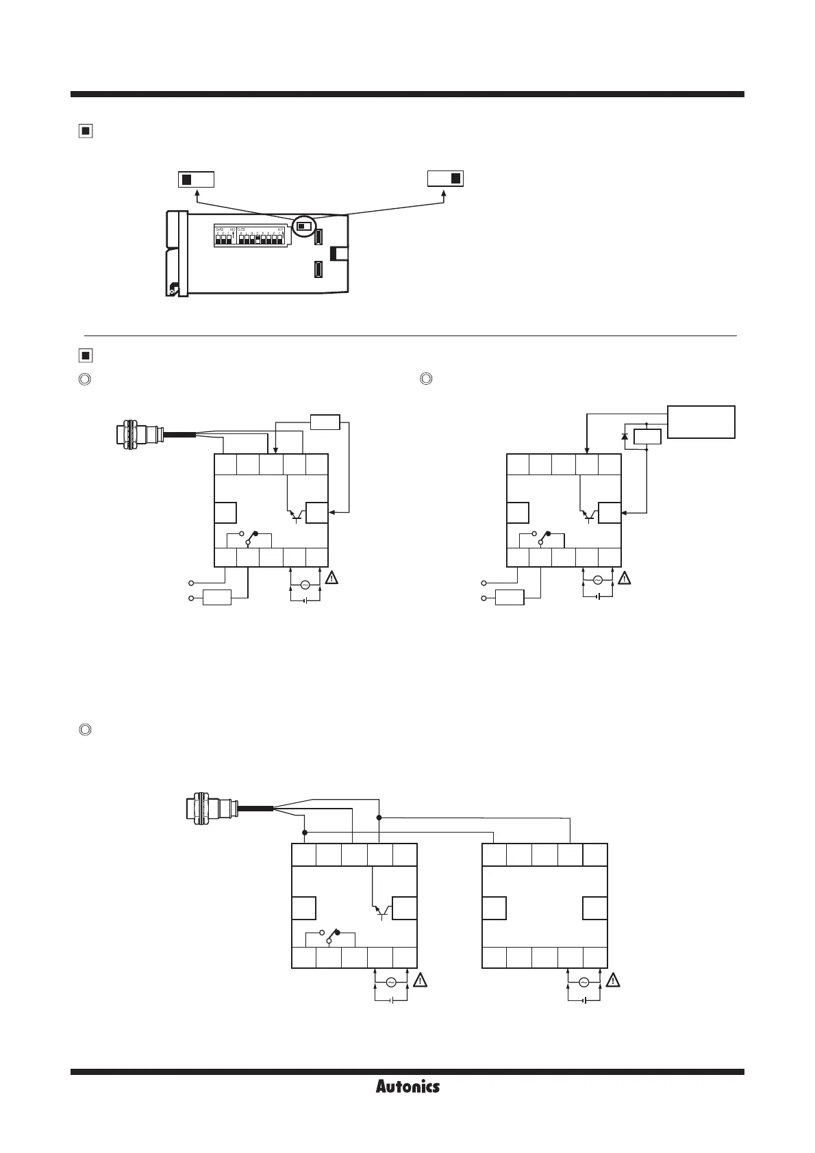
RESET
RESET
SOURCE
SOURCE
1122334455
6677889910 10
12
--++
CP1 CP10V 0VCP2 CP2
+12V +12V
(INHIBIT)
<FX4S> <FX5S-I>
(INHIBIT)
Black
Brown
Blue
RESET RESET
SOURCE SOURCE
● Select NPN(No-voltage input)
※
Please be sure to turn OFF the power before changing input logic.
● Select PNP(Voltage input)
In case of operating the load by power supply
of the sensor
Using 2 counters with one sensor
It is available to use 2 counters with one sensor.
Please connect as the power of sensor is supplied from only one of countes and design input logic with same way.
● Please select proper capacity of load, because total
current consumption should not be exceed current
capacity.
(Max. 50mA )
● Contact capacity : Max. 250VAC 3A
●
The capacity of Load1 must not be exceed Max. 30VDC, Max.
100mA of the switching capacity of the transistor.
● Please do not supply the reverse polarity voltage.
※
Please connect the surge absorber(Diode) at both
terminals of Load1, in case of using the inductive load.
(Relay, etc.)
Input logic selection
Input & Output connections
FXS Series
 Loading...