9
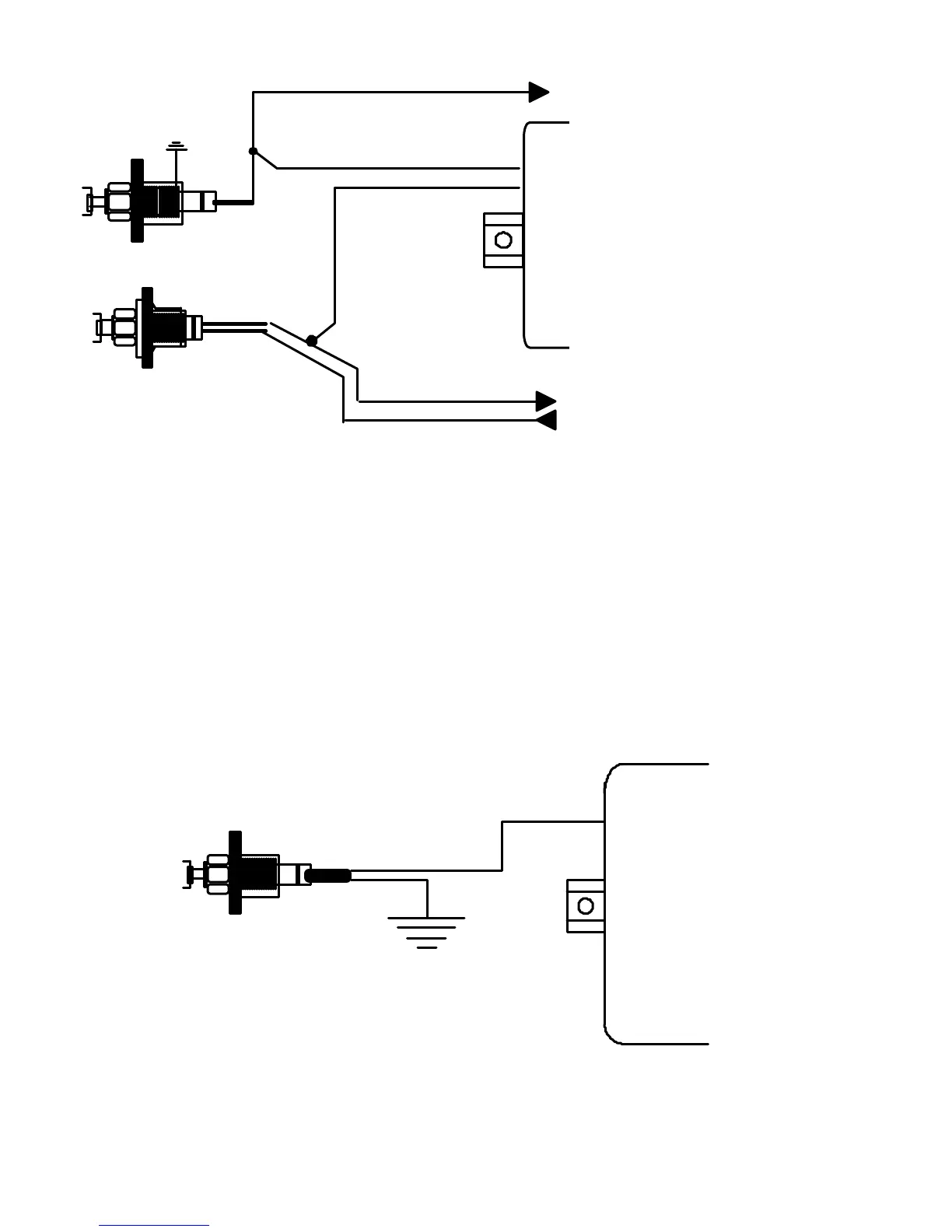
GRAY TRIGGER
INPUT WIRE
PURPLE TRIGGER
INPUT WIRE
SWITCH BODY
GROUNDED TO VEHICLE
SWITCH BODY
ISOLATED FROM VEHICLE
12 VOLT CONSTANT
SUPPLY FROM VEHICLE
TO INTERIOR LIGHTS
TO INTERIOR LIGHTS
NEGATIVE SWITCHING
POSITIVE SWITCHING
(MOST FORDS)
[FIGURE 6]
4. The PINK wire is provided for the installation of optional AutoPage sensors for added security. Install and adjust the
chosen sensor according to the sensor’s installation instructions.
5. Select a suitable location and install the CALL (*) button. Connect the GREEN wire
from the AP4000EX 6 wire harness to one side of the call button. Connect the remaining
wire from the call button to vehicle ground.
(*) Do not eliminate the CALL button. It must be used to program the pager.
6. Connect the BLACK main ground wire to a solid ground as close to the control unit as possible. Keep the ground
wire as short as possible.
CALL SWITCH
(MOMENTARY SWITCH)
GREEN
 Loading...