3
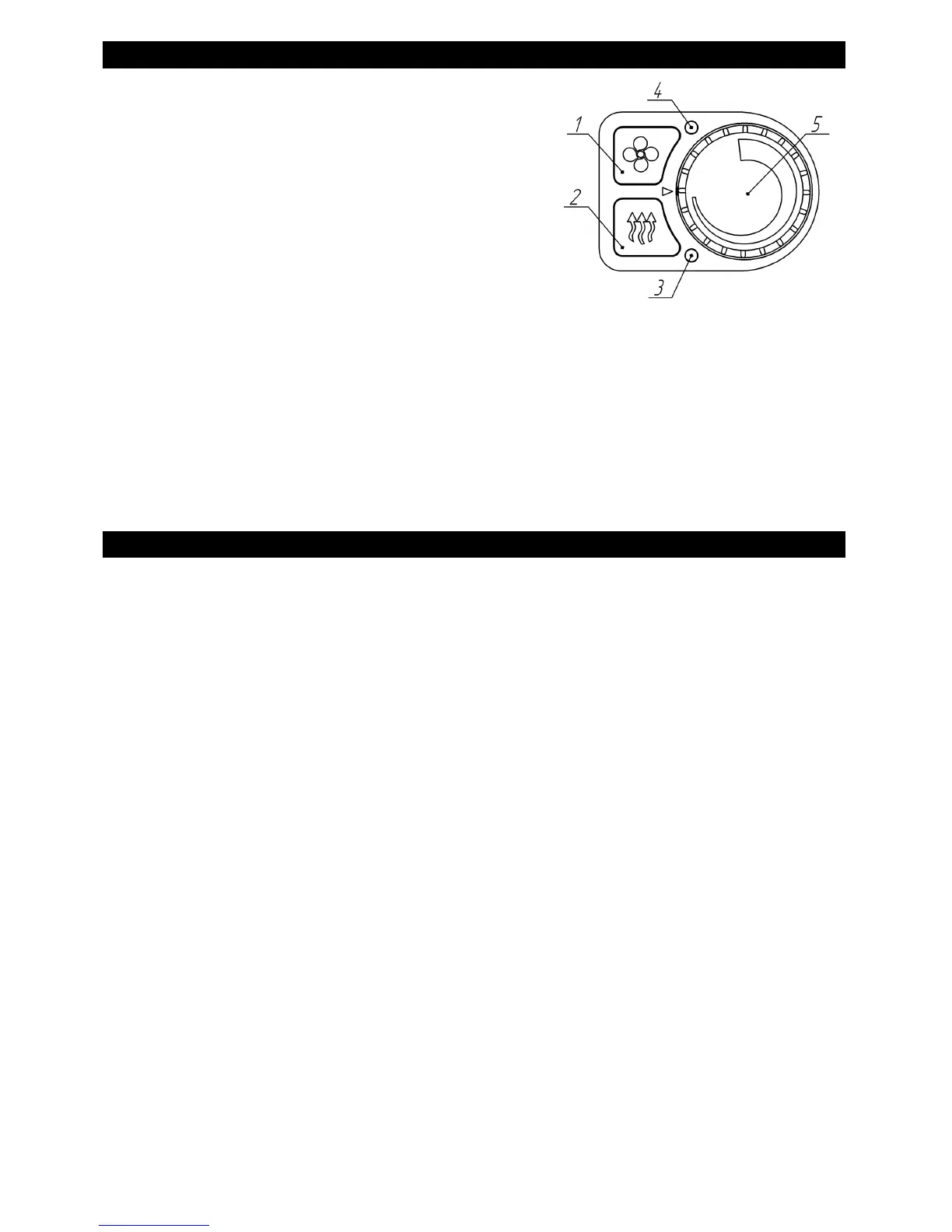
PU-5 control panel .
The following are located on the front of the panel:
1 – Ventilation mode on/off button;
2 – Heater on/off button;
3 – Operation LED display;
4 – Ventilation mode LED display;
5 – Potentiometer knob.
The LED in Pos. 3 indicates the heater status:
- yellow light - heating mode;
- fast blinking yellow – during purging;
- slowly blinking red - in case of malfunction;
- off - heater is not operational.
The LED in Pos. 4 indicates the ventilation mode status:
- green light - interior sensor is not connected and heater operates in ventilation
mode;
- green blink - ventilation mode off;
- yellow light - the interior sensor is connected and the heater operates in heating
mode with ventilation function;
- off - heater is not operational, with ventilation mode off.
Using the control panel .
When the heater is connected to the vehicle electrical circuit, the display pos. 4 fast
blinks green to display the connection process.
The button pos. 1 is designed to:
- switch the ventilation mode on and off;
- switch the ventilation function on and off in heating mode (if the interior sensor is
connected).
The button pos. 2 is designed to switch on the heater in heating mode (for an unlimited
time) and switch the heater off.
The regulator pos.5 is intended for:
- regulations of speed of rotation of the fan on the ventilation mode;
- regulations of heating capacity of a heater from "min" to "max" of kW on the heating
mode;
- regulations of desirable air temperature from 1 °C (or 15 °C *) to 30 °C on the
heating mode.
* - Depending on the heater model and production year.
 Loading...