PAGE
4 OF 5
SIREN
Connect the bonnet switch to the single black wire coming out of the
siren. Feed the thick black multicore wire through a grommet into the
vehicle interior and connect up as shown on page 1.
INTERIOR LIGHT (SELECTABLE) (SEE 4.0 & TABLE 1 note 8.3)
The interior light illumination is connected to the negative door wire (Blue
wire). The light will fade on and off. See table 1 (8.3) Pg 2 for feature
selection.
NOTE : If the vehicle has positive door switching this feature can still be
wired using an additional relay but without the fade facility. (SEE WIRING
DIAGRAM PAGE 1)
HAZARD PULSE
To check that the ‘Hazard Pulse’ mode is suitable for a particular car,
access the back of the vehicle’s hazard light switch and momentarily
connect a ground (via a 5Amp fuse) to the switched side. The hazard
lights should start flashing and will continue to flash until the ground wire
is connected again to the same point on the switch. If the test is
satisfactory, enable ‘hazard’ while programming (Table 1 option 8.9) and
connect the yellow wire from the alarm to the switched side of the hazard
light switch.
QUICK TEST
To enter quick test, enter the Program Code, 1,2,3. The arming time and
the siren time are shortened to facilitate quick and easy testing. To exit
quick test, do not trigger the alarm for a period of two minutes and the unit
will exit automatically. Alternatively, select any programmable feature.
PROGRAMMING NEW REMOTE CONTROLS
b. Enter each digit of the code using the flashing LED and ignition
switch. After entering the last digit, the LED will flash rapidly for 2
seconds.
c. Enter the two digit code 1, 1 leaving the ignition ON after the final digit.
The LED will flash rapidly for two seconds.
d. Transmit with the new remote for approximately half a second,
pausing for half a second between each transmission, until the LED
flashes rapidly indicating that the remote is now programmed. Further
remotes may now also be programmed.
e. Note that if a seventh transmitter is programmed into the alarm
system it will override the first code learnt. To remove all transmitters,
fill the 6 memory spaces with 6 new transmitters, or a single
transmitter 6 times.
f. To exit program mode, eit her wait for 10 seconds without transmitting
or switch the ignition off.
PROGRAMMING NEW WIRELESS SENSORS (Optional Sensors)
The unit has the ability to learn up to 6 wireless sensors.
To program, refer to the 5 digit user code supplied with the unit or the
code attached to the control module and proceed as follows:
Note that if Hazard functionality is available on CANBus, this
feature may still need to set up
Whilst the alarm is not supplied with any remotes, the unit has the ability
to learn up to 6 remotes.
To program, refer to the 5 digit user code supplied with the unit or the
code attached to the
a) The process is started in one of two ways.
i) Switch the ignition on/off 5 times in 10 seconds
ii) Press and hold the Valet Mode button for 5 seconds or more.
The example will continue using the Ignition switch to select digits.
a) The process is started in one of two ways.
i) Switch the ignition on/off 5 times in 10 seconds
ii) Press and hold the Valet Mode button for 5 seconds or more.
The example will continue using the Ignition switch to select digits.
depending on your vehicle (Consult the
specific vehicle information).
control module and proceed as follows.
The following are however identical in functionality:
The following are however identical in functionality:
.....
.....
....
.....
.....
.....
.....
.....
.....
.....
9.0
10
11
12
13
14
Turning ON and keeping the
Ignition ON
Turning OFF and keeping the
Ignition OFF
<Or>
<Or>
Pressing and holding the Valet
Mode Button
Releasing the Valet Mode
Button.
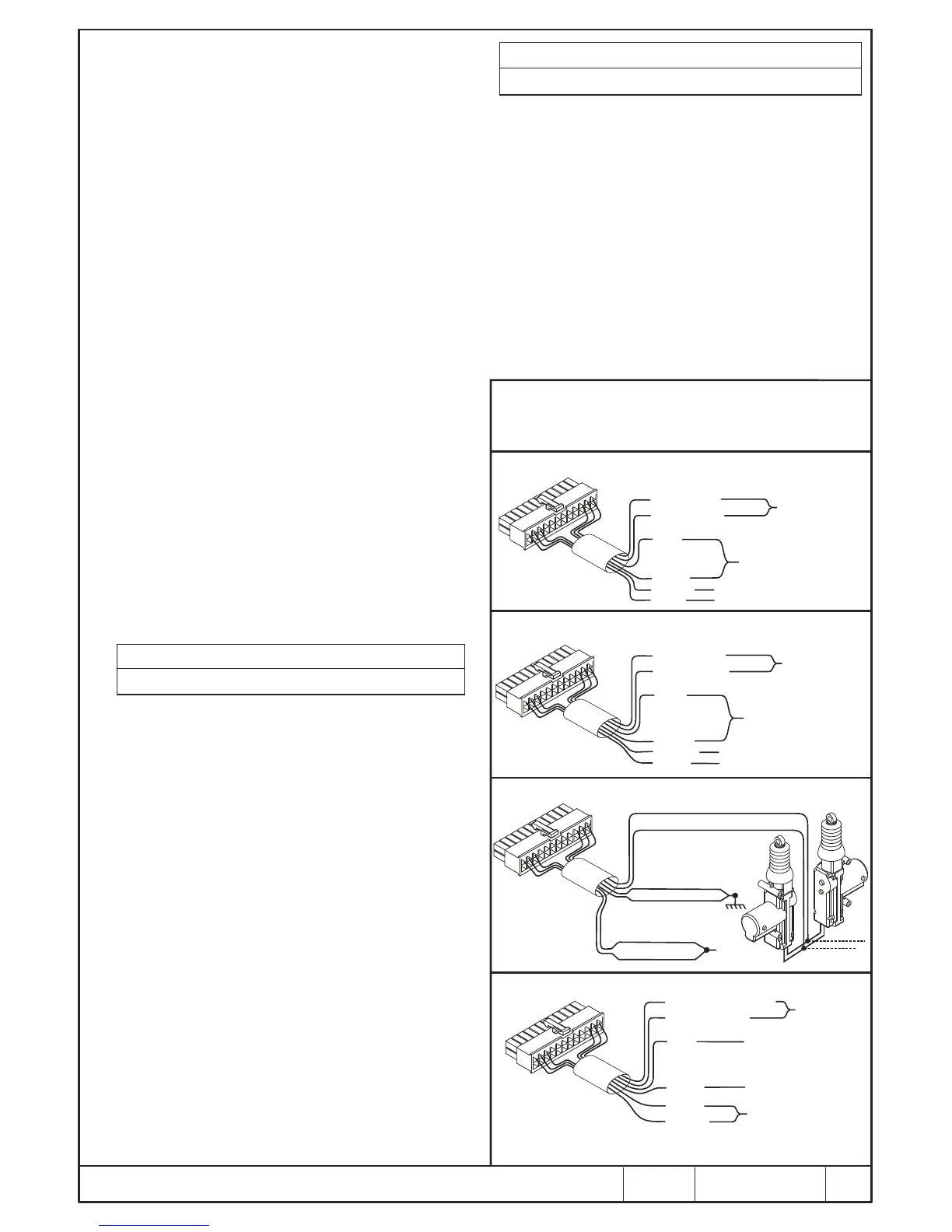
POSITIVE TO LOCK AND POSITIVE TO UNLOCK
ALTERNATE POSITIVE
BLUE - UNLOCK
BROWN
GREEN - LOCK
JOIN TO VEHICLE’S
CENTRAL LOCKING
CONTROL WIRES
CONNECT BOTH WIRES TO
A +12V FUSED LINE (20 AMP)
GREY
NOT CONNECTED. INSULATE WELL
NOT CONNECTED. INSULATE WELL
VIOLET
YELLOW
S
L
E
E
VE
D
NEGATIVE TO LOCK AND NEGATIVE TO UNLOCK
HIGH CURRENT - ALTERNATE NEGATIVE
BLUE - UNLOCK
BROWN
GREEN - LOCK
JOIN TO VEHICLE’S
CENTRAL LOCKING
CONTROL WIRES
CONNECT BOTH WIRES
TO A RELIABLE BATTERY
NEGATIVE/EARTH POINT
ON THE VEHICLE
GREY
NOT CONNECTED. INSULATE WELL
NOT CONNECTED. INSULATE WELL
VIOLET
YELLOW
S
LE
EV
E
D
ALTERNATING POLARITY - TO DRIVE 4 SLAVE MOTORS
BLUE COMMON UNLOCK
GREEN COMMON LOCK
YELLOW N/C UNLOCK
VIOLET N/C LOCK
BROWN N/O LOCK
GREY N/O UNLOCK
+ 12 V
(FUSED 20A)
S
L
E
E
EV
D
PNEUMATIC PUMP CONTROL (MERCEDES BENZ)
BLUE - TO PUMP MOTOR
BROWN
VIOLET - TO DOOR
JOIN TOGETHER AND
INSULATE WELL WITH TAPE
NOTE :
A longer pulse duration is required for the pumps to operate efficiently.
The longer pulse duration is selectable. See note 1.4 & Table 1 (9,9)
GREEN
YELLOW
CUT CONTROL
WIRE AND JOIN
AS SHOWN
CONNECT TO A +12V
FUSED LINE (20 AMP)
GREY
CONNECT TO A RELIABLE
EARTH POINT
S
L
E
E
V
E
D
CENTRAL LOCKING CONFIGURATIONS
NOTE : The 446 RLC has full central locking capability on board.
Connector outputs - as per diagram.
Turning ON and keeping the Ignition
ON
Turning OFF and keeping the
Ignition OFF
<Or>
<Or>
Pressing and holding the Valet
Mode Button
Releasing the Valet Mode Button.
b. Enter each digit of the code using the flashing LED and ignition switch.
After entering the last digit, the LED will flash rapidly for 2 seconds.
c. Enter the two digit code 3, 3. The LED will flash rapidly for two seconds.
d. Within 8 seconds activate the wireless sensor. The LED will turn on, and
a barp will be heard indicating that the sensor has been detected. Within
5 seconds, the sensor needs to be added into a zone. To add it into the
same zone as the hardwired movement sensors press the “Arm/Lock”
on the alarm transmitter. To add it to an independant wireless sensor
zone press the Off/Unlock button and a barp will be heard to confirm
successful programming.
e. Note if neither the On or Off button is pressed within 5 seconds of
receiving a wireless sensor signal the sensor will not be added to
memory. You can still activate an alternate sensor for an additional 5
seconds and then program it into the required zone.
f. To exit program mode, wait for 10 seconds or switch the ignition off.
....
....
....
AUTOWATCH 446 RLC ALARM WIRING DIAGRAM
DPFK 695/522
REV. 2
01/04/09
 Loading...