NORMALLY
OPEN:
DO NOT
CONNECT
GP RELAY
PFK PART
NO.436 900
GP RELAY
PFK PART
NO.436 900
NORMALLY
OPEN:
DO NOT
CONNECT
87
87
87a
87a
86
86
85
85
30
30
+12V
+12V
CONNECT TO SELECTIVE UNLOCK FROM ALARM
BLUE
BLUE
GREEN
BLUE
UNLOCK
UNLOCK
UNLOCK
UNLOCK
UNLOCK
UNLOCK
UNLOCK
UNLOCK
GREEN
BROWN
BROWN
BROWN/WHITE
BROWN/WHITE
LOCKLOCK
LOCK
LOCK
LOCK
LOCK
LOCK
LOCK
COMMON
COMMON
DRIVERS
DOOR
MOTOR
DRIVERS
DOOR
MOTOR
DRIVERS
DOOR
MOTOR
FRONT
PASSENGER
DOOR
MOTOR
FRONT
PASSENGER
DOOR
MOTOR
PASSENGER
AND REAR
DOOR
MOTORS
REAR
PASSENGER
DOOR
MOTORS
REAR
PASSENGER
DOOR
MOTORS
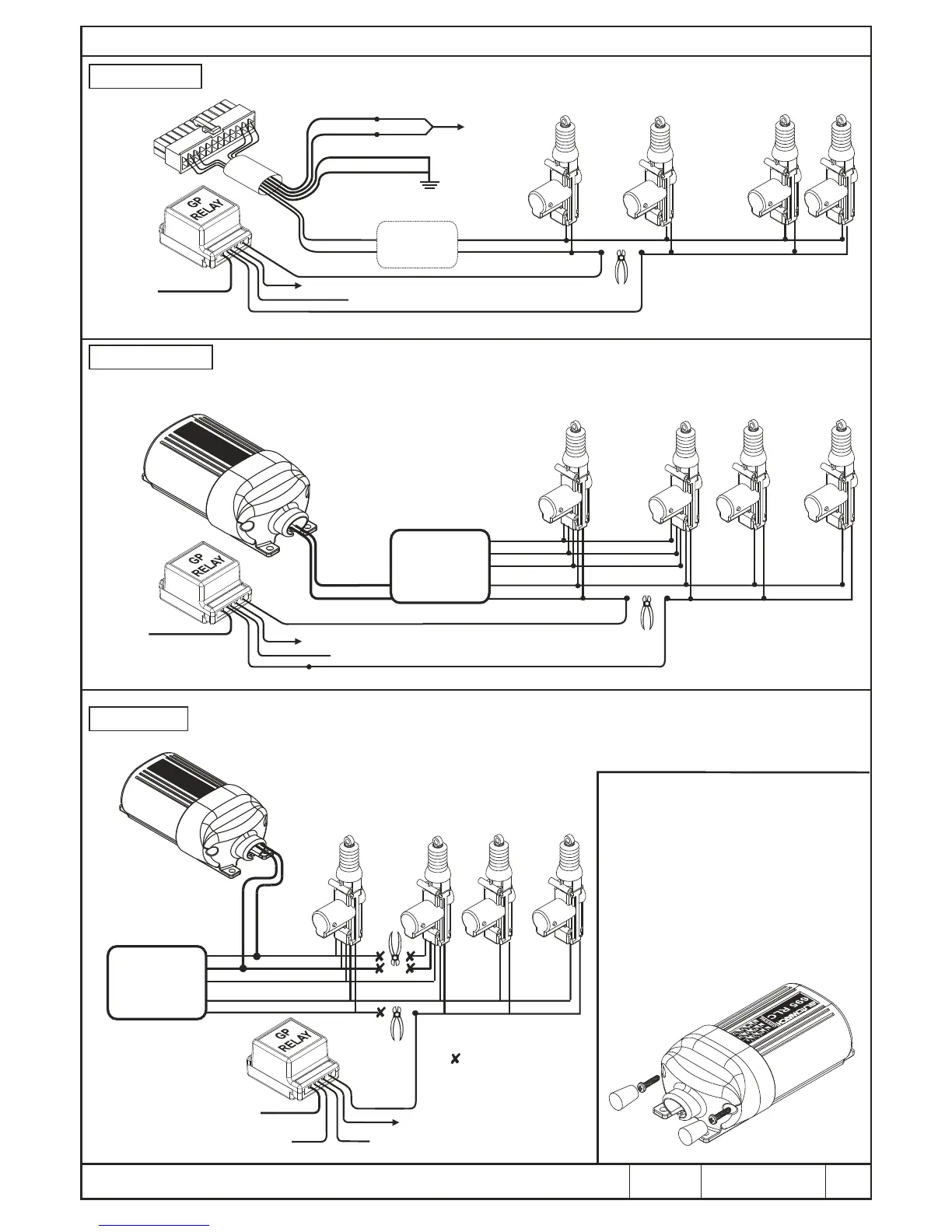
THIS CONFIGURATION IS IDEAL WHEN USING SLAVE DOOR MOTORS
+ 12 VOLTS
(FUSED 20A)
GREY
BROWN
VIOLET
YELLOW
ALTERNATING
POLARITY
CENTRAL
LOCK
MODULE
CENTRAL
LOCK
MODULE
NOTE :
Following this modification, the passenger
doors will no longer unlock when the driver's
door is unlocked manually.
CONNECT TO SELECTIVE UNLOCK FROM ALARM
SELECTIVE UNLOCKING WIRING OPTIONS
PAGE
5 OF 5
OPTION 1A
OPTION 2
THIS CONFIGURATION IS IDEAL FOR MODIFYING
FACTORY FITTED CENTRAL LOCKING MOTORS
OPTION 1 (B)
THIS CONFIGURATION IS IDEAL WHEN INSTALLING A 4-DOOR CENTRAL LOCKING KIT
A
A
L
R
M
UN
I
T
A
L
A
R
M
UN
I
T
# The 'active' polarity is the opposite
polarity of the motors at rest.
CUT AND INSULATE
CONNECT TO SELECTIVE UNLOCK FROM ALARM
+12V
GP RELAY
PFK PART
NO.436 900
NORMALLY OPEN:CONNECT TO
GROUND OR +12V AS REQUIRED
TO DRIVE MOTORS #
87
87a
86
85
30
CONNECT TO 'REST STATE' OF MOTOR WIRES
(determined by the polarity of the motors at rest)
Once the installation is complete and fully
tested the security cover can be fitted.
Ensure that the slide in the security
housing is not fitted and route all the wires,
with the exception off the LED and
MOVEMENT SENSOR wires, through the
slot and fit the slide.
Attach the security housing to the main
casing using the screws provided and
insert the anti-tamper Screw caps.
FITTING THE SECURITY HOUSING
S
L
EE
V
E
D
AUTOWATCH 446 RLC ALARM WIRING DIAGRAM
DPFK 695/522
REV. 2
01/04/09