Line of Sight Infrared Hydrocarbon Gas Detector AutroPath HC800 , 116-P-HC800/IGB, Rev. A, 2016-03-03
P/N 95-8744, v4.2 , rev. 3/16
Autronica Fire and Security AS
Page 42
ONLINE
1) Process variables
2) Device Diagnostics
3) Configure/setup
Process Variables
1) Gas xxxxxxx
2) PV x.xx LFL-M
3) PV %rnge 0.00%
4) Loop current x.xx mA
5) Device temp. x.xx Deg C
6) GAS URV x.xx LFL-M
7) GAS LRV x.xx LFL-M
8) Gas trend
Device Info
1) Cfg change count xxx
2) Write protect Yes/No
3) Universal rev 7
4) Fld dev rev xx
5) Software rev xx
6) RX flash CRC xxxx
7) TX Flash CRC xxxx
Sensor Info
1) Active last flash xxxxx
2) Reference last flash xxxxx
3) Active avg xxxxx
4) Ref avg xxxxx
5) Active normalized xx
6) Reference normalized xx
7) Ratio x.xx
8) Absorption x.xx
9 Gain xxxxx
Gain Mode xxxxx
Flash counts xxxx
Device Temp. x.xx deg C
Tx lamp voltage xxxx
Fault and Status bits
1) Device status
2) More Device Status
3) Advisory faults
4) More advisory faults
5) Detection disable faults
6) Transmitter Faults
7) More Transmitter Faults
8) Transmitter Status
Alignment info
1) Active xxxxxxx
2) Reference xxxxxxx
3) X – Axis xxxxx.xx
4) Y – Axis xxxxx.xx
5) Z – Axis xxxxx.xx
History
1) Max Temp
2) Min Temp
3) Running hrs
4) Event Log
5) Cal Log
General Info
1) Manufacturer xxxxxxx
2) Model xxxxxxxx
3) Tag xxxxxxxxx
4) Long tag xxxxxxxxx
5) Descriptor xxxxxxxxx
6) Message xxxxxxxxx
7) Final Asmbly Num xxx
8) Dev ID xxxxxxxxx
9) Date **/**/**
Detector Setup
1) Reset latched alarms
2) Zero cal
3) Span cal
4) D/A trim
5) Gen config
6) Hart Config
7) RS-485 setup
8) Gas type setup
9) Alarm setup
RTC Setup
Sensor setup
Output loop setup
Data Protection
Restore factory defaults
Hart Configuration
1) Tag xxxxxx
2) Long tag xxxxx
3) Descriptor xxxxxx
4) Message xxxxxx
5) Poll Address xxx
6) Num Req Preams 5
7) Num Resp Preams 5
8) Date xxxxxx
9) Final asmbly num xxxxxx
RS-485 Settings
1) Poll addr xxx
2) Baud Rate
3) Parity
Baud Rate
1) 9600
2) 19.2K
3) 38.4K
4) 57.6K
5) 115.2K
Parity
1) None
2) Even
3) Odd
Gas Type Setup
1) Gas
2) Unit
Gen Configuration
1) Processing Mode xxxx
2) PV Units xxx
3) Green LED setting xxxx
4) Green LED turn off time xx
5) Rx Heater Control ->
6) Tx Heater Control ->
Alarm setup
1) Low Alarm Level xxx
2) Low Alarm Latch xxx
3) High Alarm Level xxx
4) High Alarm Latch xxx
5) Low alarm relay NE/DNE
6) High alarm relay NE/DNE
RTC Setup
1) Seconds xx
2) Minutes xx
3) Hours xx
4) Day xx
5) Month xx
6) Year xx
Data Protection
1) Enter Password
2) Write Protect
3) Write Protect On/OFF
Write Protect
Not Protected
Protected
Change Password
Rx Heater Control
1) Heater mode xxxxxxx
2) Heater power
3) Heater turn on temp xxx
4) Heater cut off voltage xxxx
Advisory Faults
1. Zero Calibration Fault ON/OFF
2. Span Calibration Fault ON/OFF
3. Beam Block ON/OFF
4. Ref Sensor Saturated ON/OFF
5. Active sensor Saturated ON/OFF
6. Input voltage Low ON/OFF
7. Zero Drift ON/OFF
8. Undefined ON/OFF
Detection Disable Faults
1. Ram Fault ON/OFF
2. Data Flash Fault ON/OFF
3. Flash CRC Fault ON/OFF
4. AFE Fault ON/OFF
5. Heater Fault ON/OFF
6. Internal voltage fault ON/OFF
7. Undefined ON/OFF
8. Undefined ON/OFF
More Device Status
1. Low Alarm Active ON/OFF
2. High Alarm Active ON/OFF
3. Response Test Active ON/OFF
4. Self Test Active ON/OFF
5. Multidrop mode Active ON/OFF
6. Interim Beam Block ON/OFF
7. Detector disposition ON/OFF
8. Undefined ON/OFF
Sensor Setup
1) Processing Mode xxxx
2) Interconnect mode xxxx
3) Log Interim beam block Y/N
4) Gain Mode xxxx
5) Gain xx
6) Tx lamp voltage xxxx
7) Auto voltage during cal E/D
8) Beam block fault time xxx
More Advisory Faults
1. Output Loop Fault ON/OFF
2. Low signal Fault ON/OFF
3. Interconnect Fault ON/OFF
4. Cal Line low Fault ON/OFF
5. Input voltage high ON/OFF
6. Undefined ON/OFF
7. Undefined ON/OFF
8. Undefined ON/OFF
RTC
1) Seconds xx
2) Minutes xx
3) Hours xx
4) Day xx
5) Month xx
6) Year xx
Device Status
1. Warming up ON/OFF
2. Any Fault ON/OFF
3. Calibration Active ON/OFF
4. Output loop fixed ON/OFF
5. Alignment Active ON/OFF
6. Configuration change ON/OFF
7. Temperature over range ON/OFF
8. Undefined ON/OFF
Output loop setup
1) Read back fault setting ON/OFF
2) Output fault mode xxxxx
3) Detection disable fault level x.xx
4) Configuration fault level x.xx
5) Advisory fault level x.xx
Device Diagnostics
1)Response test
2)Loop test
3) General info
4) Device info
5) Sensor info
6) Fault and Status bits
7) History
8) RTC
9) Alignment info
Tx Heater Control
1) Heater mode xxxxxxx
2) Heater power
3) Heater turn on temp xxx
4) Heater cut off voltage xxxx
Transmitter Faults
1 .Input voltage Low ON/OFF
2. Trigger voltage ON/OFF
3. High voltage ON/OFF
4. Input voltage High ON/OFF
5. Ram Fault ON/OFF
6. Data Flash fault ON/OFF
7. Flash CRC Fault ON/OFF
8. Heater Fault ON/OFF
More Transmitter Faults
1. Internal voltage ON/OFF
2. Software Fault ON/OFF
3. Undefined ON/OFF
…
8. Undefined ON/OFF
Transmitter Status
1. Warm-up ON/OFF
2. Any Fault ON/OFF
3. Config Change ON/OFF
4. Temperature over-range ON/OFF
5. Output loop fixed ON/OFF
6. Modbus unlocked ON/OFF
7. Self test active ON/OFF
8. Undefined ON/OFF
Gas
1) Methane
2) Propane
3) Butane
4) Special
Unit
LFL-M
PPM-M
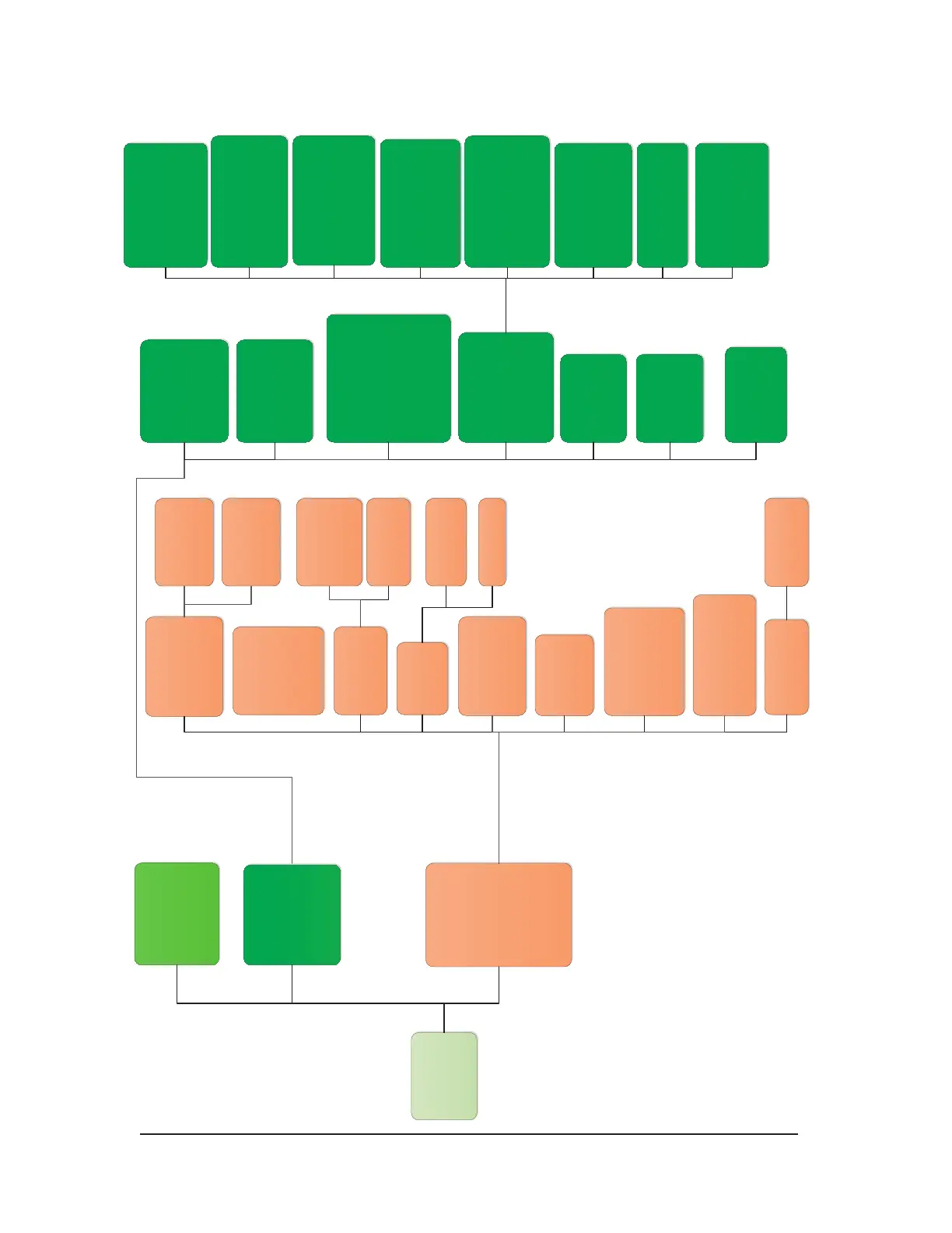
AUTROPATH HC800 HART MENU STRUCTURE
This section displays the menu trees for the AutroPath HC800. The Menu tree shows the primary commands and
options available when using menu selections.
 Loading...