Bar
Copper pipe
Clamp handle
Red arrow mark
Cone
Yoke
Handle
Bar
"A"
Fig.57
D: Flaring work
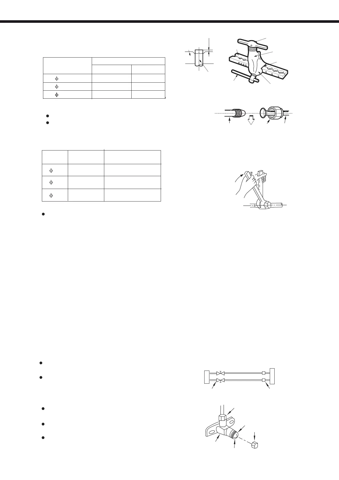
Firmly hold copper pipe in a die in the
dimension shown in the table below.
Outer diam.
(mm)
A(mm)
Max.
Min.
6.351.3
0.7
9.53
1.61.0
12.7
1.8
1.0
12.7
1.8
1.0
Align the center of the pipes.
Sufficiently tighten the flare
nut with fingers, and then tighten
it with a spanner and torque wrench
as shown in Fig.58 & 59
Excessive torque can break nut
depending on installation conditions.
Fig.59
Indoor unit tubingFlare nutPipings
Fig.58
Outer
diam.
Tightening
torque(N.cm)
Additional tightening
torque(N.cm)
6.35
12.7
9.52
1500
(153kgf.cm)
1600
(163kgf.cm)
3500
(357kgf.cm)
3600
(367kgf.cm)
2500
(255kgf.cm)
2600
(265kgf.cm)
Air and moisture in the refrigerant system have undesirable effects as indicated below:
● Pressure in the system rises.
● Operating current rises.
● Cooling or heating efficiency drops.
● Moisture in the refrigerant circuit may freeze and block capillary tubing.
● Water may lead to corrosion of parts in the refrigeration system.
Therefore, the indoor unit and tubing between the indoor and outdoor unit must be leak tested
and evacuated to remove any noncondensables and moisture from the system.
●
Preparation
Check that each tube(both liquid and gas side tubes) between the indoor and outdoor units
have been properly connected and all wiring for the test run has been completed. Remove
the service valve caps from both the gas and the liquid side on the outdoor unit. Note that
both the liquid and the gas side service valves on the outdoor unit are kept closed at this
stage.
●
Pipe length and refrigerant amount:
When relocate the unit to another place,
perform evacuation using vacuum pump.
Make sure the refrigerant added into the air
conditioner is liquid form in any case.
Outdoor
unit
Indoor
unit
Refrigerant
Packed valve
Half union
Gas side
Liquid side
A
C
D
B
Fig.65
Open the valve stem until it hits against the
stopper. Do not try to open it further.
Securely tighten the valve stem cap with a
spanner or the like.
Valve stem cap tightening torque (See
Tightening torque table in previous page ).
Flare nut
Stopper
Cap
Valve body
V
alve stem
Fig.66
Tightening connection
Air purging
Caution
Air purging w ith vacuum pump
Caution in handling the pack ed valve
REFRIGERANT PIPE CONNECTION
39
 Loading...