Do you have a question about the AUX ASW-H12B4/E Series and is the answer not in the manual?
Provides essential information for ordering replacement parts correctly.
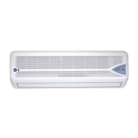
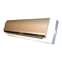
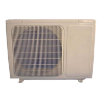
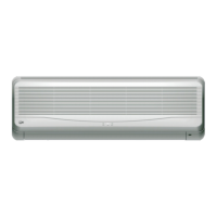
Displays visual representations of different indoor unit models.
Explains the coding system used for product model identification.
Details comprehensive technical data and specifications for various models.
Describes the functions and operation of the remote control unit.
Provides step-by-step instructions for operating the air conditioner.
Illustrates the internal wiring for specific indoor unit models.
Depicts the internal wiring schematics for another set of indoor units.
Outlines initial checks and common inspection points for issues.
Guides on diagnosing and resolving issues related to no power display.
Provides troubleshooting steps for when the indoor fan motor fails to operate.
Offers solutions for problems where the outdoor unit is unresponsive.
Details troubleshooting procedures for a non-functional step motor.
Addresses issues where heating mode is active but no hot air is produced.
Outlines steps to troubleshoot a non-responsive remote control.
Analyzes potential failures and resistance measurements for key components.
Shows a visual breakdown of the indoor unit's components.
Lists all parts of the indoor unit with corresponding codes and quantities.
Provides a visual exploded diagram of the outdoor unit's assembly.
Enumerate the components of the outdoor unit with part details.
Illustrates the exploded view of the indoor unit's controller assembly.
Lists the parts associated with the indoor unit's controller.
Defines key terms and symbols used throughout the manual.
Explains how to activate and use the forced operation mode.
Details the automatic operation mode and its conditions.
Describes the functionality and parameters of the cooling operation mode.
Explains the dehumidifying mode and its operational characteristics.
Outlines the operation and settings specific to the fan-only mode.
Details the heating mode, including temperature and fan speed controls.
Describes functions to prevent cold air blow and manage residual heat.
Explains the safety mechanism to prevent overheating.
Details the function of the auxiliary electric heater.
Describes the intelligent defrosting process and its conditions.
Explains the sleep mode for energy saving and comfort.
Details the programmable timer functions for operation scheduling.
Outlines the self-diagnostic procedure for the unit.
Lists error codes and their corresponding causes for fault diagnosis.
Explains the louver's angle settings and their meanings.
Details the resistance values for different fan speed options.
Describes advanced functions like power break-off memory and I feel.
Explains the operation of the negative ion generation feature.
| Cooling Capacity | 12000 BTU/h |
|---|---|
| Power Supply | 220-240V, 50Hz |
| Refrigerant | R410A |
| Type | Split System |
| Outdoor Unit Dimensions | 700 x 245 x 544 mm |
| Operating Temperature (Cooling) | 18°C to 43°C |