EasyManua.ls Logo

AUX ASW-H12A4/E Series User Manual

AUX ASW-H12A4/E Series
44 pages
To Next Page IconTo Next Page
Page #1 background imageLoading...
Page #1 background image
Service Manual
Contents
1.Important Notice.............................................1
2.Technical Specification................................2-9
3.Operation Details.....................................10-13
4.Wiring Diagram.......................................14-15
5.Troubleshooting Guide.............................16-23
6.Explosion View And Parts List..................24-31
7.Refrigeration Cycle Diagram........................32
8. Control Functions Exposition..................33-42
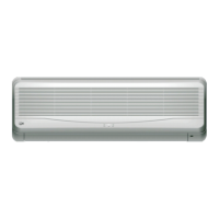
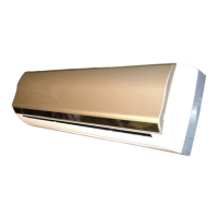
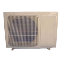
Split type Wall Mounted Air Conditioner
E series

Table of Contents

Question and Answer IconNeed help?

Do you have a question about the AUX ASW-H12A4/E Series and is the answer not in the manual?

AUX ASW-H12A4/E Series Specifications

General IconGeneral
BrandAUX
ModelASW-H12A4/E Series
CategoryAir Conditioner
LanguageEnglish

Summary

Technical Specification

2-3 Product Technical Specification Diagram

Detailed technical specifications for various models.

2-3 Product Technical Specification Diagram(continue)

Continuation of detailed technical specifications for various models.

Troubleshooting Guide

5-1The Foremost Inspecting Items

Initial checks and fundamental inspection points for troubleshooting.

5-2 No Power Display

Troubleshooting steps for issues related to no power display.

5-3 The Indoor Fan Motor Does Not Work

Diagnostic procedures for when the indoor fan motor fails to operate.

5-4 The Outdoor Unit Does Not Work

Troubleshooting steps when the outdoor unit does not function.

5-5 The Step Motor Does Not Work

Diagnostic procedures for a non-operational step motor.

5-6 Heating Mode Can Work, But No Hot Air Blow

Troubleshooting steps for heating mode issues with no hot air.

5-7 Remote Control Can Not Work

Steps to diagnose and resolve issues with the remote control.

5-8 The Failure Analysis Of The Main Parts

Analysis of common failures in main components and their resistance measurements.

Refrigeration Cycle Diagram

Function Exposition

8-12 Self-inspection

Procedure for initiating and understanding the unit's self-inspection process.

8-13 Failure Indicating

Information on error codes displayed by the unit for failure indication.

Related product manuals