User Manual
8 www.AvantcoEquipment.com
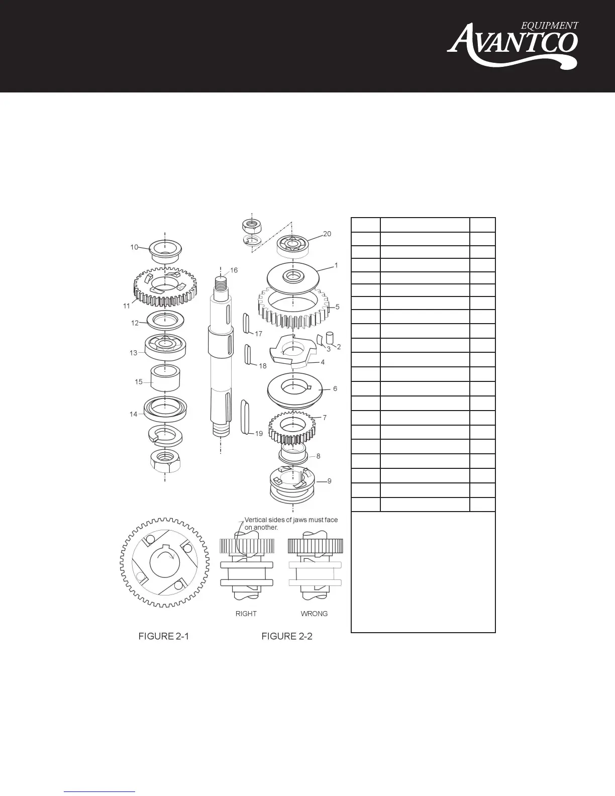
PLANETARY SHAFT ASSEMBLY
FIGURE 2
TRANSMISSION SHAFT
FIGURE 3
ITEM DESCRIPTION QTY
1 Bearing 1
2 Transmission Axle 1
3 Key 5*11 1
4 Key 5*11 1
5 Gear 1
6 Stop Ring 1
7 Gear 1
8 Stop Ring 1
9 Bearing 6201 1
NOTES:
• At the center in the shaft unit. To the
above gear is the gear shaft and gear
shaft I (see figure 3-1)
• C-type stop ring (6/8) has to be fixed
when reassembling.
• Be sure that the keys are inserted for
each gear.
ITEM DESCRIPTION QTY
1 Baffle 1
2 Roller 4
3 Spring 8
4 Engager 1
5 Gear Ring 1
6 Dividing Ring 1
7 Joint Gear I 1
8 Bearing Ring 1
9 Joint 1
10 Bearing Ring 1
11 Joint Gear I 1
12 Ring 1
13 Bearing 6205 1
14 Oil Seal Pd30*45*10 1
15 Sleeve 1
16 Axle 1
17 Key 6*14 1
18 Key 5*35 2
19 Key 6*30 1
20 Bearing 1
NOTES:
• Be sure to install correct position (see
Figure 2-1) and lubricate all of the pins
in the sleevedrive when reassembling.
• Joint (9) must always be raised and
lowere d smoothly. Be sure joint
slee
ve as shown in Figure 2-2
• Check oil seal (14), if serious oil
leaks from drip cup.