5
ENG
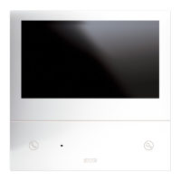
VI2F-PIT7WF
INDOOR STATION WITH 7" TOUCH SCREEN WI-FI RANGE 2 WIRE V44 EASY
1) OVERVIEW
The VI2F-PIT7WF device is an audio/video indoor station for the AVE V44 EASY 2-wire video intercom system.
The functions and characteristics are as follows:
Audio/Video/Buttons:
• 7" horizontal touch screen;
• Hands-free;
• Touch buttons: entrance opening, muting, camera display;
• Remote management via AVE VIDEO V44 APP;
Warnings:
• Missed call;
• Door open;
• Active ringer muting;
Video intercom functions:
• Call answering;
• Display of analogue cameras via dedicated VI2F-CAM interface;
• Management of outside door auxiliary bell
• Management of three gates, two on board the outdoor station and one optional on auxiliary relay VI2F-RELAY;
• Communication between devices in the same flat or other flats
2) DECLARATION OF CONFORMITY
The VI2F-PIT7WF device complies with the following standards:
• EN 62820-1-1:2016 Building intercom systems - Part 1-1: System requirements – General grade2
• RoHS Directive 2011/65/EU;
• REACh Regulation (EC) No. 1907/2006;
• RED Directive 2014/53/EU (only where applicable): The full text of the EU Declaration of Conformity is available at the following Internet address: www.ave.it
3) INSTALLATION, POSITIONING AND FIXING
The device should be installed at a height of 1.5 m from the ground. Screw the screws supplied to secure the support bracket to the rectangular box, after it has been horizontally recessed.
Once wiring operations have been completed, align the slots in the back of the monitor with the bracket hooks (1) and slide the device slightly downwards (2).
ATTENTION: the device is equipped with a Wi-Fi card. If a system features more than no.1 art. VI2F-PIT7WF, it is necessary to install a "local" power supply (art. VI2F-ALI600MA) for each device.
Check the maximum absorptions of the devices installed in order to avoid high absorptions on the bus which would compromise correct operation.
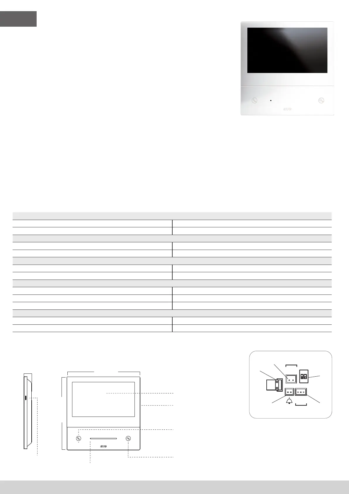
4) CONNECTIONS
The meanings of the connection terminals and dip-switches on the rear of the device are shown below:
➀ AUXILIARY POWER SUPPLY
Terminal 1 + 30 VDC
Terminal 2 GND
➁ 2 Wire BUS
Terminal 1 BUS A
Terminal 2 BUS B
➂ Bell (cable supplied with the device)
Terminal 1 Door bell input
Terminal 2 GND
➃ Interface for RS485 extension (indoor use only)
Terminal 1 DB
Terminal 2 MD
Terminal 3 GND
➄ DIP SWITCH
DIP 1 - MASTER/SLAVE ON = indoor station MASTER OFF = indoor station SLAVE
DIP 2 - END OF LINE IMPEDANCE (activate if the indoor station is the last one in the branch) ON = impedance ON OFF = impedance OFF
5) VARIOUS FUNCTIONS
4
Answering a call
Press to answer/close an incoming call.
While monitoring the outdoor camera, without a call in progress, pressing
the button enables communication.
Unlock electric locks
No function in Stand-by mode;
During an incoming call and/or conversation, a short press unlocks the
power relay (Unlock 1) of the outdoor station, a long press (3 sec) activates
the clean contact relay (Unlock 2).
179 mm
25 mm
179 mm
RC
NC
M
S
1 2
ON
BUS
BUS
DB
DA
GND
RS485
VI2F-PIT7WF
+30V
GND
POWER
179 mm
179 mm
RC
NC
M
S
1 2
ON
BUS
BUS
DB
DA
GND
RS485
VI2F-PIT7WF
+30V
GND
POWER
25 mm
179 mm
RC
NC
M
S
1 2
ON
BUS
BUS
DB
DA
GND
RS485
VI2F-PIT7WF
+30V
GND
POWER
SD card
Touch screen
Speaker
Microphone
 Loading...