7
GB GB
INTENDED USE
The stands of the Strato Safe Family are designed to support luminaires for lm and broadcast
productions on location or in the studio.
The product is for professional use only.
TECHNICAL SPECIFICATIONS
SPECIFICATIONS FOR SAFE OPERATION
1. Ensure you read these instructions carefully, before using this product,
2. Respect the Maximum load as shown in the technical specication chart.
3. Operation temperature range -20°C - +60°C
4. This product should be used by experienced personnel only.
5. Ensure that the ground on which this product is being used is stable and can withstand the weight
of the stand and the payload of the item attached.
6. Ensure that the central column is perfectly level before attempting to raise any item that is attached.
7. Do not adjust the base with a load mounted and/or raised.
8. Before positioning the stand and attempting any kind of adjustment/movement of the stand, ensure that
there are no obstacles, electric, cables or hazards located in the area occupied by the stand and
its load.
9. Ensure that the attached item is correctly locked onto the top attachment and completely stable.
10. The stands of the Strato Safe family are designed to support luminaires.
11. All loads should be balanced especially when using T Bars.
12. During outdoor use with a height exceeding 2.2 m (86.6”) it is advised to set up the product utilizing
anchor wires and or wind brace kits. (087WBK, sold separately).
13. Periodically check that the stand is in good condition (see chapter “MAINTENANCE”).
14. Do not leave the product unattended when working in high trac areas where others could
interfere with the stand.
MOD B7018
B7043CS-1 B7047CS-1 B150P-1 B150-1
Minimum length (cm) 105 155 172 201 190
Maximum length (cm) 175 427 467 621 610
Folded length (cm) 126 185 209 236 225
Footprint diameter (cm) 120 182 213 213 213
Weight (Kg) 27 60 62 93.4 76
Maximum load (Kg) 100 70 70 70 70
Socket size (mm) 28 28 28 28 28
Sections 2 4 4 5 5
OPERATING ENVIRONMENT ,
Transportation and handling of the stand must be carried out by at least two operators in
compliance with the regulations relating to the handling of loads.
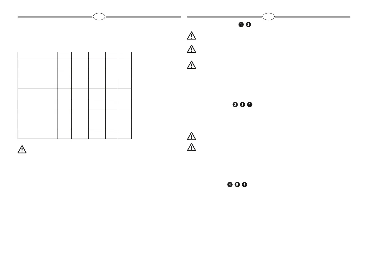
To move the stand using a winch or other lifting gear, lift or lower the stand with a webbing sling
(not included) around the upper spider as shown in (g 1).
While lifting or lowering, verify that the stand is well balanced and that the legs are retracted.
Never load webbing slings beyond their maximum carrying capacity and check that it is correctly
xed to the stand and to the lifting gear.
1.2 The stand must only be used on horizontally level surfaces.
1.3 The stand must be set up on rm ground capable of taking both the weight of the stand and its
load without any of the wheels sinking in, which could cause the stand to tip over. If the ground is soft,
place a board “B” (g.2) under the wheels.
SETTING THE STAND UP , ,
2.1 After checking that the stand is set up on rm ground, release the wheel locks if wheels are tted
“F” (g. 4). Unlock knob “E” (g. 4) and push the bottom central column casting down so that the stand
legs are fully open and then tighten knob “E” (g. 4) to keep in place.
The stand wheels must be locked before loading it “F” (g. 4).
Ensure that the column is level using the levelling bubble.
It is essential that the stand be levelled BEFORE loading it with equipment.
When setting up the stand, use caution to avoid pinching/crushing hazards due to the movement
of legs or of other parts.
2.2 On stands operating at heights in excess of 2.2 m (86.6”) or in windy conditions, a wind bracing kit
should be used “D” (g. 3) and should always be used when the horizontal wind load on the lighting
body exceeds the value of 3.5 Kg (35 N). The anchoring of the braces cables to the ground is the
responsibility of the user, who will have to evaluate the best solution to x the braces by means of ground
spikes or anchors (not supplied with the product) according to the conformation of the ground itself.
LOADING THE STAND , ,
3.1 Ensure the stand wheels are correctly locked as per 2.1.
3.2 All riser columns on the stand should be lowered and knobs “G” (g. 4) tightened.
3.3 Check to ensure the xture locking knob “H” (g. 5) is unscrewed enough to allow a 28 mm (1
1/8”) pin to t into the top of the stand.
3.4 Once the load has been mounted on the stand, lock it securely by tightening knob “H” (g. 5).
3.5 All loads should be balanced especially when using “T” bars etc. (g. 6).
3.6 In windy conditions, we recommend not loading the stand with products that have wide surfaces
 Loading...