The Weigh-Tronix Monorail Installation Guide describes the installation, maintenance, and operation of a monorail scale system, including both static and in-motion models. This guide provides step-by-step procedures to ensure proper setup and functionality of the weighing unit within an existing monorail system.
Function Description
The Weigh-Tronix monorail scale is designed to accurately measure the weight of items transported on a monorail system. It integrates into an existing monorail line, replacing a section of the rail with a weighing unit. The system utilizes two weight sensors, whose outputs are combined in a junction box (J-box) to send a single weight signal to an indicator. This allows for precise weight measurement, which can be used for various purposes such as inventory control, quality assurance, or process monitoring.
The system supports both static and in-motion weighing. In the static model, items are weighed when stationary on the live rail. For the in-motion model, the scale is equipped with limit switches (S1 and S2) that trigger the start and stop of the averaging process as a trolley passes over the weighing unit. This enables continuous weighing without stopping the flow of items on the monorail. The WI-130 indicator, used with the in-motion model, averages the weight as the trolley passes and displays the result, which can then be used for accept/reject decisions based on predefined setpoints.
The system's core components include:
- Weighing Unit: Comprises a back frame, weigh bar, and live rail, which replaces a section of the existing monorail.
- Junction Box (J-box): Connects the two weight sensors and combines their outputs into a single signal for the indicator. It also houses potentiometers for balancing the weight sensors and adjusting the deadload offset.
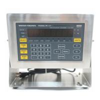
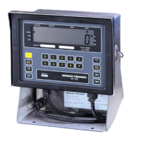
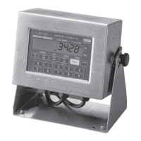
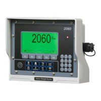
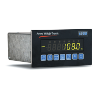
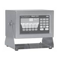
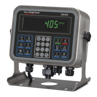
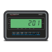
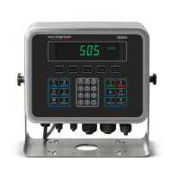
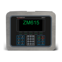
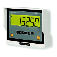
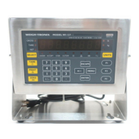
- Indicator (e.g., WI-130, WI-127, WI-110/WI-120): Processes the weight signal from the J-box, displays the weight, and, for in-motion models, manages averaging, setpoints, and accept/reject outputs.
- Rail Hangers: Used to support the weighing unit and the ends of the existing monorail.
- Limit Switches (for in-motion models): Sensors (S1 and S2) that detect the presence and passage of a trolley, triggering the start and stop of the weighing process.
The WI-130 indicator, specifically, uses setpoints to define the start and stop of averaging, as well as accept and reject outputs. It displays the average weight (WT) and allows users to set minimum and maximum acceptable values using the F1 key. When a trolley triggers the entrance sensor (setpoint #1), the WI-130 begins averaging and turns off accept/reject outputs. When the exit sensor (setpoint #2) is triggered, averaging stops, the average weight is displayed, and accept/reject outputs are activated based on the set values.
The WI-127 indicator also supports in-motion weighing with similar functionality, using specific wiring for set input (exit trigger) and reset input (entrance trigger). The WI-110 and WI-120 indicators can be configured for in-motion print switch connections, allowing external switches to trigger print requests, while the DATA SEND key on the indicator remains active.
Usage Features
The monorail scale is designed for integration into existing monorail systems, providing a seamless weighing solution.
- Installation: The installation process involves removing a section of the existing monorail, drilling holes in the dead rails, and mounting the weighing unit using standard rail hangers. It is crucial to ensure the unit is level both lengthwise and from front to back for accurate measurements. Angle iron or similar bracing material can be added to the back frame for additional support and to minimize vibration. Interface cables must be routed and secured to prevent pinching, cutting, or snagging by monorail operations.
- In-Motion Weighing: For in-motion models, limit switches are connected to the control cable. These switches detect the trolley's movement, initiating and concluding the weighing cycle automatically. This feature is ideal for high-throughput environments where continuous operation is essential.
- Indicator Configuration: The indicators (e.g., WI-130, WI-127, WI-110/WI-120) are configurable to meet specific operational needs. For the WI-130, setpoints can be defined for start averaging, stop averaging, accept output, and reject output. The F1 key allows users to set minimum and maximum acceptable weight values.
- Remote I/O (Optional): The SSCU-8 Remote Expanded I/O configuration is an optional feature for controlling Accept/Reject devices. This involves setting specific switches on the I/O expansion board and installing OPTO 22 modules.
- Sensor Connections: Detailed wiring diagrams are provided for connecting entrance and exit sensors to the WI-130 main board (TB14) and the WI-127 (TB15), ensuring correct signal transmission for in-motion operations. For earlier revision main boards, +5Vdc can be used from a serial connector instead of +12Vdc.
- Print Switch Connections: For WI-110 and WI-120 indicators, external print switches can be connected to trigger print requests, enhancing operational flexibility. This requires specific software versions and PC card configurations.
Maintenance Features
The manual outlines key maintenance procedures to ensure the longevity and accuracy of the monorail scale.
- Weigh Bar Replacement: If a Weigh Bar needs replacement, the process involves removing the live rail, disconnecting the Weigh Bar cable from the junction box, driving out the roll pin, and then removing the defective Weigh Bar. The replacement Weigh Bar must be inserted correctly, ensuring the "T" mark on the shaft is facing up, and then secured with the roll pin. The cable is reconnected, and the live rail is re-mounted. This procedure highlights the modular design of the Weigh Bar, facilitating easy replacement.
- Weight Sensor Balance Adjustment: This is a critical procedure for maintaining the accuracy of the scale. The J-box contains potentiometers (R2 and R3 for weight sensors, R1 for deadload offset) that allow for balancing the outputs of the two weight sensors. The adjustment process involves:
- Removing the J-box cover to access the potentiometers.
- Zeroing the indicator with an empty trolley.
- Placing a calibrated test weight (minimum 25% of capacity) directly over one weight sensor and recording the displayed value.
- Removing the weight and verifying the display returns to zero.
- Repeating the process for the other weight sensor.
- If the displayed weight values for the sensors vary by more than ±1 division, the J-box potentiometers must be adjusted. A formula is provided to calculate the number of 360° turns required for the potentiometer, with clockwise turns for positive values and counterclockwise for negative values.
- This process is repeated until all weight sensors are equal within ±1 scale division.
This detailed balancing procedure ensures that both weight sensors contribute equally to the overall measurement, maintaining the scale's precision.
- Cable Management: Proper routing and securing of interface cables are emphasized during installation to prevent damage and ensure reliable operation. This proactive approach minimizes the risk of cable-related malfunctions.
- Troubleshooting Guidance: While not explicitly detailed as a separate section, the step-by-step nature of the installation and maintenance procedures implicitly guides users in identifying and resolving common issues, such as ensuring proper leveling, correct cable connections, and accurate sensor balancing. For complex issues, users are directed to contact the Weigh-Tronix Service Department, particularly for older software versions or specific hardware configurations.