Do you have a question about the Avery Weigh-Tronix ZM405 and is the answer not in the manual?
Covers installation procedures, including torque specifications and cable grounding.
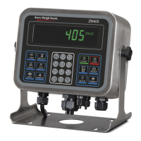
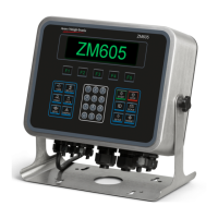
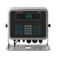
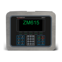
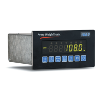
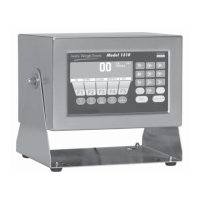
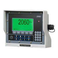
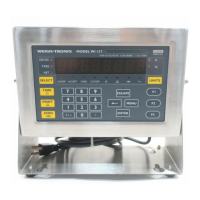
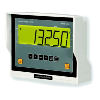
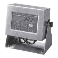
Describes the ZM400 series front panels, including keys and display.
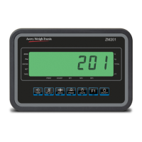
Details how to enter alphanumeric values on the ZM401 using its keys.
Explains how to use the alphanumeric keypad on the ZM405 for data entry.
Outlines the steps to access the indicator's menus using passwords.
Explains the Quick Code feature for rapid navigation to menu sections.
Describes the User menu for setting time, date, site ID, and viewing seal status.
Explains how to display audit counters for configuration and calibration.
Describes the Diag menu for checking indicator performance and diagnostic tests.
Explains how to view scale output in A to D counts or mV/V.
Details how to view and clear the current zero offset.
Introduces submenus for configuring scale operation parameters.
Covers Zero, Span, and Linearity calibration, and printing reports.
Explains how to configure scale parameters like capacity, division, and units.
Details system parameters like defaults, display modes, and tare functions.
Guides on configuring communication ports and protocols for device connection.
Explains SMA protocol commands and responses for scale communication.
Lists ENQ and B-Cast commands and their corresponding functions.
Describes NCI commands for weight requests, status, and unit changes.
Covers PLC configuration settings for Modbus/TCP and Ethernet/IP.
Describes the analog output card providing proportional output to scale weight.
Explains current loop/RS485/RS422 communication with connected devices.
Details the USB Device option card for connecting USB host devices.
Describes the wireless Ethernet card for 802.11g connectivity.
Explains the AC relay card converting logic outputs to AC solid state relays.
Covers connecting a second analog scale with 5VDC excitation.
Details connecting a second analog scale with 10VDC excitation and STVS.
Explains connecting to external I/O interfaces for SSCU8 or 16 Position I/O boards.
Covers connecting up to four 120-240VAC inputs.
Explains how to create custom print formats using tokens and variables.
| Brand | Avery Weigh-Tronix |
|---|---|
| Model | ZM405 |
| Category | Accessories |
| Language | English |