Do you have a question about the Avery Weigh-Tronix WI-150 and is the answer not in the manual?
Overview of the service manual's content.
Details the three operating modes: operations, test, and configuration.
How to seal the unit to prevent configuration changes.
Explains the function of the keypad buttons and layout.
Steps to enter configuration and set SC-150, units, capacity, division.
Configuring density, zero range, stability, and AZT parameters.
Setting cutoff control, tare, display update, and averaging.
Setting up serial ports, baud rate, parity, and stop bits.
Customizing print layout, commands, and options.
Setting security codes, ID, cutoffs, and time/date formats.
Customizing the physical arrangement of printed information.
Overview of the default print command order.
Explanation of ASCII codes used for custom text.
Procedures for modifying the print layout commands.
Steps for deleting or adding ASCII codes within strings.
Steps to adjust dead load offset before calibration.
Steps to access the configuration menu for calibration.
Procedures for setting calibration points.
Explains when the reset menu becomes active.
Steps to reset setup, adjust, or data to defaults.
Procedures for removing the indicator stand and separating the unit.
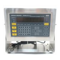
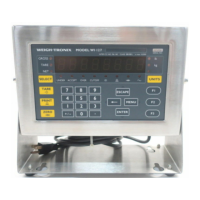
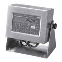
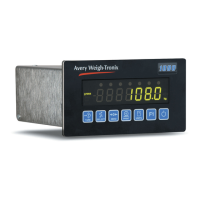
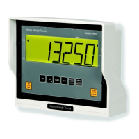
Overview of the WI-150 indicator's main components.
Block diagrams for SC-150 and Fiber-Link board options.
Description of components on the main PC board.
Description of components on the A/D PC board.
Itemized parts for the BP-150 battery pack.
Description of the BC-150 battery charger PC board.
Parts list for the PS-150 power supply, old style.
Parts list for the PS-150 power supply, new style.
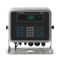
Comprehensive list of parts for the SC-150 remote control.
Details of available interface boards for the SC-150.
Identification of SC-150 main board and cutoff I/O interface board.
Identification of dual serial and RS-485 interface boards.
Diagram showing connections on the SC-150 main PC board.
Outline dimensions and board details for Fiber-Link RS-422.
Details of Fiber-Link current loop and RS-232 PC boards.
Details of Fiber-Link analog and cutoff PC boards.
Visual representation of the WI-150 indicator keypad.
Electrical schematic illustrating the WI-150 indicator circuitry.
| Brand | Avery Weigh-Tronix |
|---|---|
| Model | WI-150 |
| Category | Accessories |
| Language | English |