Do you have a question about the Avery Weigh-Tronix ZM510 and is the answer not in the manual?
Covers the procedures for installing the ZM510 indicator, including torque specifications and grounding.
Provides essential safety guidelines for handling and replacing batteries in the indicator.
Outlines the necessary steps for regular maintenance to ensure proper operation and longevity of the device.
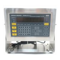
Details the function and operation of each key on the ZM510 indicator's front panel for user interaction.
Explains the methods and keys used to navigate through the indicator's menu system effectively.
Describes functions for setting time, date, Site ID, checking seal status, and viewing archive information.
Provides access to information about the indicator's software, firmware, serial number, and installed options.
Allows viewing of scale values, including A to D counts and mV/V output for diagnostic purposes.
Enables testing of serial ports (1-3) and the USB port for communication functionality.
Verifies the proper functioning of external switches connected to the indicator's input ports.
Checks if external relays or lights connected to the indicator's outputs are wired correctly and functioning.
Guides through the procedures for calibrating the scale, including zero, span, and linearity adjustments.
Covers configuration of scale parameters like capacity, division size, units, stability, and filtering.
Allows configuration of system parameters such as site defaults, display modes, button functions, and update settings.
Details the configuration of communication ports (Serial, Ethernet) and protocols for connecting external devices.
Covers the enabling and configuration of various optional cards that can be installed in the indicator.
Explains the Scale Manufacturers Association (SMA) protocol, including commands and responses for scale communication.
Provides information on configuring the indicator for communication with Programmable Logic Controllers (PLCs).
Details the settings for the S1 switch banks on option cards for proper operation.
Describes the analog output card, its specifications, and jumper settings for proportional weight output.
Shows an example of a report detailing the indicator's configuration settings and parameters.
Displays an example of a report generated after the scale calibration procedure.
Presents an example of an audit log report, showing changes made to parameters over time.
Explains how to create and customize print formats by inserting characters, tokens, and variables.
Provides step-by-step instructions on how to modify existing print strings, including inserting and deleting characters.
Details how to add dynamic data like tokens and variables to print strings for customized output.
Lists and explains firmware tokens used for generating print data, including their parameters and available values.
Provides a reference for network tokens used in PLC and network communication, detailing their data types and usage.
A graphical overview of the ZM510 indicator's menu structure, showing navigation paths for Admin, Setup, User, and Audit functions.
Provides a visual breakdown of the ZM510 indicator's components for identification and assembly reference.
Lists available parts kits for the ZM510 indicator, facilitating the ordering of necessary components.
Illustrates the ZM510 indicator's system architecture, showing connections between the main PCB, display, keypad, and modules.
Offers guidance on interfacing remote inputs and outputs using Opto-22 modules with the ZM indicator.
| Brand | Avery Weigh-Tronix |
|---|---|
| Model | ZM510 |
| Category | Accessories |
| Language | English |