3. Cable Retaining Eyelet
Small tab to hold wrapped cables in place.
4. Cable Entry Hole
An entry hole for network, power and I/O cables.
5. Power Connector Block
Accepts a terminal block with either an AC or DC power connection. DC input can be either polarity. Only
required when Power over Ethernet is not available.
6. Audio I/O Connector
Accepts a mini-jack connector (3.5 mm).
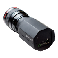
7. Ethernet Port
Accepts an Ethernet connection to a network. Server communication and image data transmission occurs
over this connection. Also receives power when it is connected to a network that provides Power over
Ethernet.
8. Safety Lanyard
Connects to the anchor on the main camera module to help prevent the camera from falling after
installation.
2 Base View
 Loading...