10
English
English
Connecting to External Devices
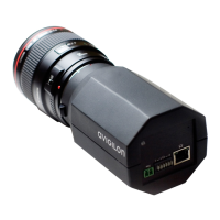
External devices are connected through the I/O terminal. The pinout
for the I/O terminal is shown in the following table and diagram.
Consult the software user guide for details on how to configure the
external devices.
Figure: External I/O terminal schematics and example application.
Table:External I/O Terminals
Pin Function Description
1 GND Ground for RS-485 interface.
2 RS-485 RX/TX+ Half-duplex RS-485 interface for controlling
external equipment
3 RS-485 RX/TX-
4 Input (-)/Output A Shared pin for Input and Output.
5 Input (+) The input uses a photocoupler and is
electrically isolated from the internal circuitry.
The input voltage should not exceed 12 V.
6 Output B The output uses a photocoupler and is
electrically isolated from the internal circuitry.
The output terminal (A and B) connections can
be made with either polarity. The output can
drive a maximum load of 50 V and 120 mA.
RS-485
1
2
3
4
5
6
24V
3V
+
+
-
-
External Device
Relay
Switch
Camera
 Loading...
