3
J1
Vout Common output (5VDC/ Batt)
Alarm 1 Cabin alarm button *
Alarm 2 Maintenance alarm button*
Filter Alarm lter *
Vout Common output (5VDC/ Batt)
EOA End of Alarm signal input
J2
LPBus Low Power Bus (LPBus) which connects to external audio units and other LPBUS devices
J6
Tra ce Required for debugging (only for Avire Technical Support)
J9
+Vin (8-28 VDC) 2-Wire System: 8-28VDC 250mA max from external power supply. CAN H and CAN L communication
connected to the DCP.
4-Wire System: Connection from DCP/CANBus Splitter. Power supply is not required, as DAU LPBus will
receive its power from DCP/ CANBus Splitter.
It is recommended to use twisted pair wiring for CAN H and CAN L.
CAN H
CAN L
-Vin (Ground)
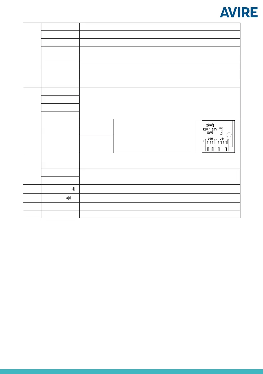
J10
Green Pictogram Please Note: 2 outputs of 12Vdc or 24Vdc are
supplied with a max current of 20mA each. The
output voltage can be selected using the SW5
switch located inside the device (default: 12Vdc).
It is possible to connect any type of indicator that
doesn’t exceed these specications.
Yellow Pictogram
Ground Negative reference
J11
MIC + External microphone connections. Please only use microphones approved by Avire.
MIC -
SPK + External speaker connections. Please only use speakers approved by Avire.
SPK -
SW4
Microphone Cong
Internal/External microphone (default: Internal)
SW3
Speaker Cong
Internal/External speaker (default: Internal)
SW2
Battery Battery Cong (Enabled/Disabled) (default: Disabled) **
SW1
DAU congurations See chapter DAU congurations
* - Only for contacts without voltage. Place an intermediate relay if any button has voltage.
** - In installations where the DAU is powered from a power supply that also has a battery backup, its internal battery may
be disconnected. In all other cases the battery should be connected, otherwise the system won’t work in the case of mains
power failure.
Note: Connections use a positive 5vdc common and all DAU programming is done via the DCP
End of Alarm (EOA): This indicates that the emergency lift trapping rescue is over and the alarm can
be turned o or reset.
Alarm Filter: The Cabin Alarm button will not activate unless the lift is in a fault condition or the
doors are closed, this lter is mostly used to prevent nuisance calls. DAU LPBus does not need to
be programmed but requires the lift signals.
Maintenance Alarm Button: This allows dialling of a dierent telephone number if a trapped person
is a member of maintenance sta (SOS number requires programming via the DCP, P030)
Cabin Alarm button: This is the main alarm button in the car operating panel which needs a voltage
free contact from the Alarm push to trigger an emergency Alarm call. The button is defaulted to
Normally Open, but can be recongured to Normally Closed (see programming guide DAU below
PC117)
LPBus (Low Power Bus): This connector allows the connection of Triphony and Inductive loop
units.
 Loading...