Operating Manual for Controller VIBTRONIC
®
SC(E)…-2
©2002 AViTEQ Vibrationstechnik GmbH Version 02/2003 4–9
4
Use only a potentiometer (limit value 1 kOhm) with linear characteristics for the
vibration-width adjuster. Shield the signal lines to guarantee electromagnetic com-
patibility if the lines exceed five metres in length!
4.2.5 Switching on/off externally
If no external connection/cut-out (release switching) is desired, terminals 12 and
13 must be connected by means of a wire bridge so that the magnetic vibrator can
be controlled.
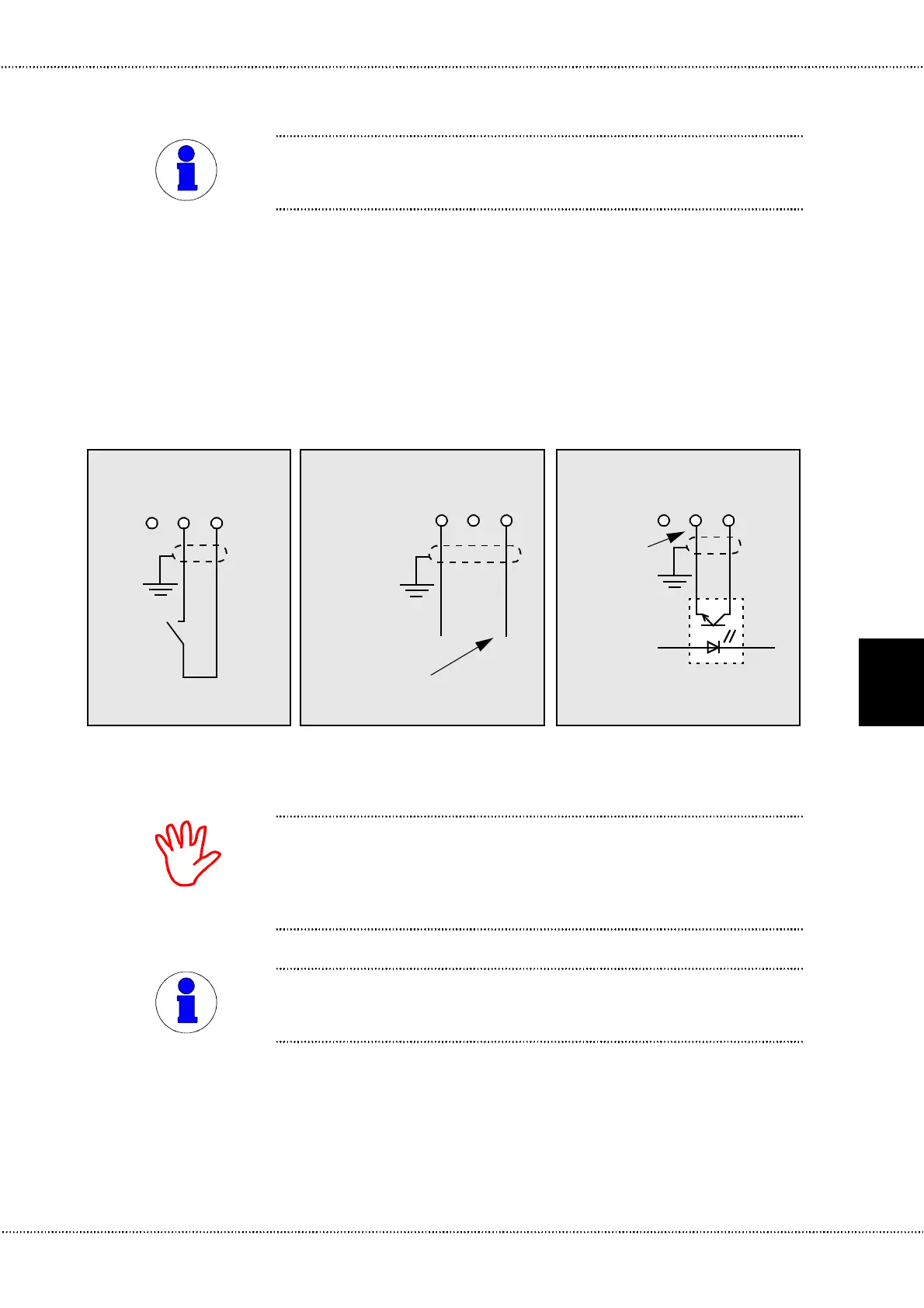
The controller can alternatively be remotely connected or cut-out by means of a
switch (relay), an optical coupler or a DC signal. The corresponding terminal
assignment possibilities are shown in see Figure 4.8.
Destruction of the controller:
note the maximum permissible load of 1 mA!
Before performing a remote connection/cut-out, always remove the factory-
installed bridge between terminals 12 and 13 as the controller may otherwise be
destroyed!
To prevent switching faults, use only gold-plated or hermetically sealed contacts.
Shield the signal lines to guarantee electromagnetic compatibility if the lines
exceed five metres in length!
NOTE
Figure 4.8 Options for switching on/off externally
12
0
I
13 (+)
5 (-)
max. +24 VDC
12 13 (+)5 (-)
–+
max. 1 mA
12 13 (+)5 (-)
Voltage sourceSwitch (voltage-free contact) Optical coupler
NOTE
 Loading...