There
is
not
one
single
capacitor
to
be found
in
the
entire
high-level signal path
of
the
A2.AII stages
are
dc-
voltage coupled. Phase shifts
in
the
audible range
are
excluded.
THE
OUTPUT
STAGE
The
output
stage circuitry
described
here
uses
two
mirror-image differential stages
at
the
front
end.
Their
working points
are
stabilized
through
electrical
sources
with
extremely
high internal resistance.
The
subse-
quent
.current
mirrors
are
responsible for
super
fast reaction times.
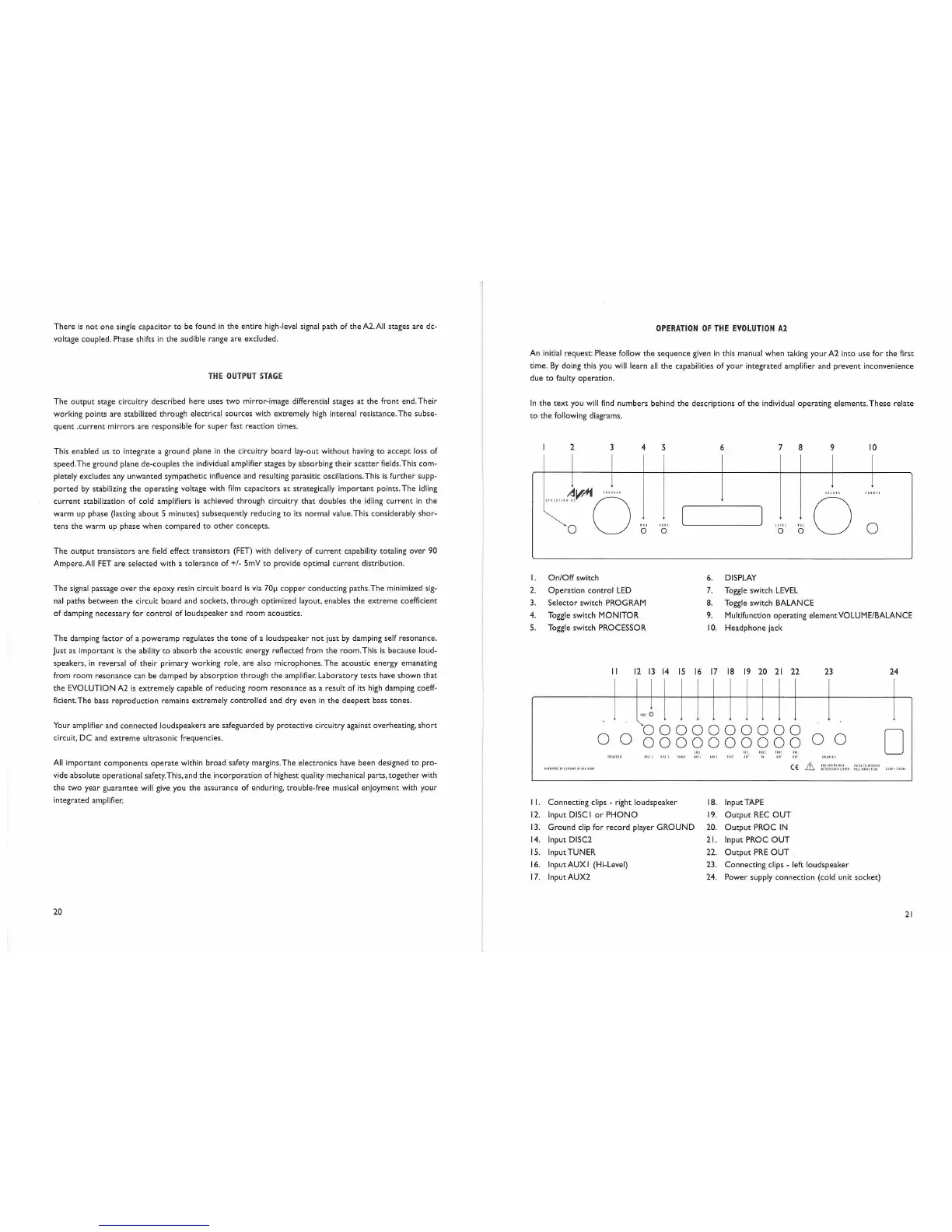
OPERATION
OF
THE
EVOLUTION
A2
An initial request: Please follow
the
sequence
given
in
this manual
when
taking
your
A2 into use
for
the
first
time.
By
doing this you will learn
all
the
capabilities
of
your
integrated amplifier and
prevent
inconvenience
due
to
faulty
operation.
In
the
text
you
will
find
numbers
behind
the
descriptions
of
the
individual
operating
elements.
These
relate
to
the
following diagrams.
This enabled us
to
integrate
a
ground
plane
in
the
circuitry
board
lay-out
without
having
to
accept
loss
of
speed.The
ground
plane
de-couples
the
individual amplifier stages
by
absorbing
their
scatter
fields. This
com-
pletely excludes any
unwanted
sympathetic influence and resulting parasitic oscillations.This
is
further
supp-
ported
by
stabilizing
the
operating
voltage with
film
capacitors
at
strategically
important
points.
The
idling
current
stabilization
of
cold amplifiers
is
achieved
through
circuitry
that
doubles
the
idling
current
in
the
warm
up
phase (lasting
about
5 minutes) subsequently reducing
to
its normal value. This considerably
shor-
tens
the
warm
up phase
when
compared
to
other
concepts.
The
output
transistors
are
field effect
transistors
(FET) with delivery
of
current
capability totaling
over
90
Ampere.AII
FET
are
selected
with a
tolerance
of
+/- 5mV
to
provide optimal
current
distribution.
2 3
4
""
o
5
'It!
o
6 7
L!l
!l
o
8
."
o
9
ID,
III
o
10
o
ill
0
0 0
0 0 0 0 0 0 0 0 0 0
0 0
0
0 0 0 0 0 0 0 0 0 0
11L1
He.
PlO!.
,ue
'"
ltlllUI
11\[,
.'HI
'''11
1111
IIll
TIrE on
"
."
on
l"lUll
CE
&
1I1"~
Irl.U
HIli
11
1P!l1l'
1111-1111,
IHIUllIIUUUTIT"'i'lI
IlTllHU!llIfl!'
"IIUIIl!lI'
12
13
14
IS
16
17
18
19
20
21
22
6.
DISPLAY
7. Toggle switch
LEVEL
8. Toggle switch BALANCE
9. Multifunction operating
element
VOLUME/BALANCE
10.
Headphone
jack
The
signal passage
over
the
epoxy
resin circuit
board
is
via
70~
copper
conducting
paths.
The
minimized sig-
nal
paths
between
the
circuit
board
and sockets,
through
optimized layout, enables
the
extreme
coefficient
of
damping
necessary
for
control
of
loudspeaker
and
room
acoustics.
The
damping
factor
of
a
poweramp
regulates
the
tone
of
a
loudspeaker
not
just
by
damping self resonance.
Just as
important
is
the
ability
to
absorb
the
acoustic
energy
reflected from
the
room.
This
is
because loud-
speakers,
in
reversal
of
their
primary working role,
are
also
microphones.
The
acoustic
energy
emanating
from
room
resonance
can be
damped
by
absorption
through
the
amplifier.
Laboratory
tests
have
shown
that
the
EVOLUTION A2
is
extremely
capable
of
reducing
room
resonance
as a result
of
its high damping coeff-
ficient.The bass
reproduction
remains
extremely
controlled
and
dry
even
in
the
deepest
bass
tones.
Your amplifier and
connected
loudspeakers
are
safeguarded
by
protective
circuitry against overheating,
short
circuit,
DC
and
extreme
ultrasonic frequencies.
All
important
components
operate
within
broad
safety margins.
The
electronics have been designed
to
pro-
vide
absolute
operational
safety.This, and
the
incorporation
of
highest quality mechanical parts,
together
with
the
two
year
guarantee
will give you
the
assurance
of
enduring,
trouble-free
musical
enjoyment
with
your
integrated ampiifier.
20
I.
On/Off
switch
2.
Operation
control
LED
3.
Selector
switch PROGRAM
4. Toggle switch
MONITOR
5. Toggle switch PROCESSOR
II
I
I.
Connecting
clips - right
loudspeaker
12.
Input DISC I
or
PHONO
13.
Ground
clip for
record
player
GROUND
14.
Input DISC2
IS. Input TUNER
16.
Input AUX I (Hi-Level)
17.
Input AUX2
23
18.
Input TAPE
19.
Output
REC
OUT
20.
Output
PROC
IN
21. Input PROC
OUT
22.
Output
PRE
OUT
23.
Connecting
clips - left
loudspeaker
24.
Power
supply
connection
(cold unit
socket)
24
21
 Loading...