6
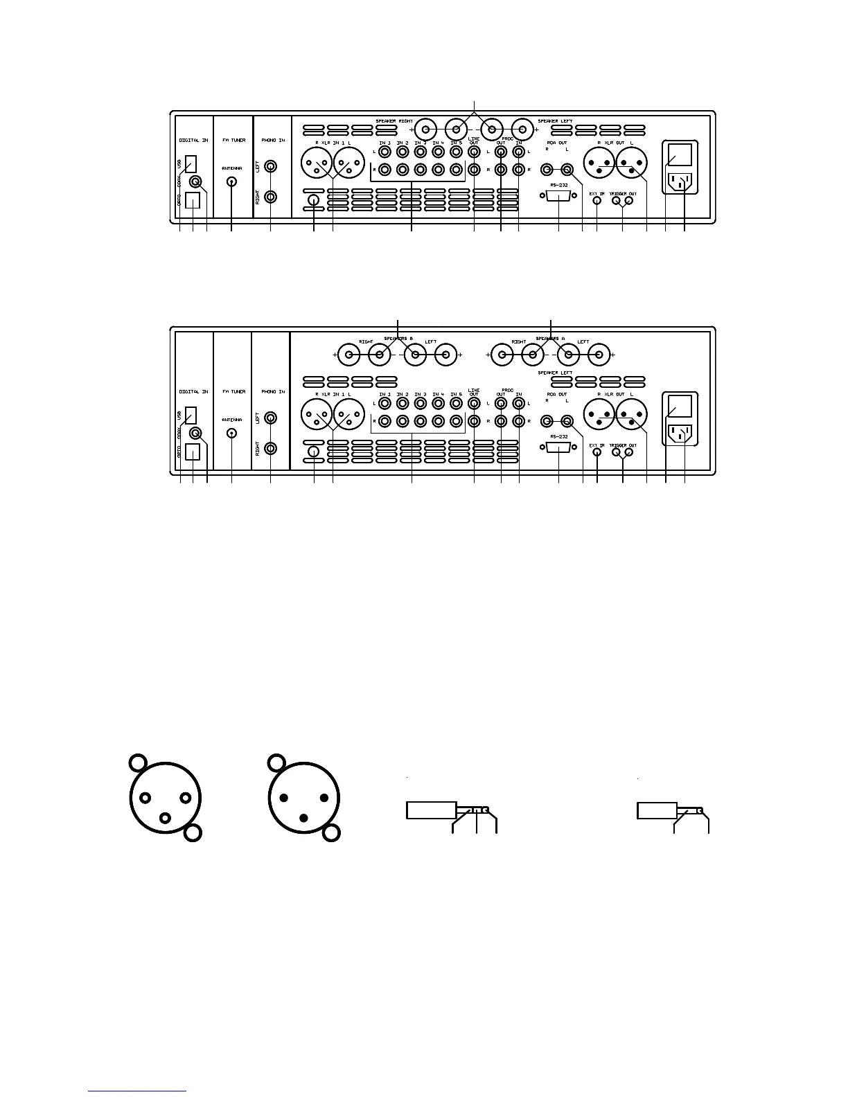
2.2.1 Rear panel PA3.2, A3.2
30
19 20 21 22 23 24 25 26 2718171615141312 2928
O
I
2.2.2 Rear panelA5.2
3231
19 20 21 22 23 24 25 26 2718171615141312 2928
O
I
12 - 14 Digital inputs (Option)
15 Antenna socket (Option)
16 Phono input (Option)
17 Ground socket for turntable chassis
18 Input 1 (XLR)
19 Inputs 1 - 5 (RCA-Cinch)
20 Output for recorder (fixed level)
21 Processor output
22 Processor input
23 RS 232 connector
24 Pre amplifier output (RCA-Cinch)
25 Connector for external IR-sensor
26 Trigger outputs
27 Pre amplifier output (XLR)
28 Mains switch
29 Mains connector
30 Speakers output, A3.2
(red = Plus, black = GND)
31 Speakers output B, A5.2
(red = Plus, black = GND)
32 Speakers output A, A5.2
(red = Plus, black = GND)
2.3 Pin configuration of connectors
1
3
2 2
3
1
3,5mm stereo
+5V supplyIR-SignalGND
infrared input
3,5mm mono
+8V tri
GND
trigger outputs
XLR-input XLR-output external IR-input(socket 25) Trigger out (sockets 26)
1 = GND (shield) 1 = GND (shield)
2 = non inverting input 2 = non inverting output
3 = inverting input 3 = inverting output