2 DSR1021/1022 Switch Installer/User Guide
The DSRIQ module is powered directly from the target device and provides Keep Alive
functionality when the DSR1021/1022 switch is not powered.
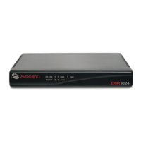
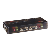
The DSRIQ-SRL (serial) module is a DCE device that provides the primary interface between a
serial device and a DSR1021/1022 switch. It provides VT100 terminal emulation, break
suppression and port history in a compact, convenient module.
Access the DSR1021/1022 switch via network connection
No special software or drivers are required on the attached, or client, computers.
NOTE: The client connects to the server housing the DSView
®
management software using an Internet
browser. For modem access, you must install DSR Remote Operations software included on the DSView 3
software D-ROM (see the DSView Installer/User Guide for more information).
Users access the DSR1021/1022 switch and all attached systems via Ethernet or using a V.34, V.90
or V.92 modem from a client computer, such as a PC. Clients can be located anywhere a valid
network connection exists.
Two modes of access to the DSR1021/1022 switch
You can access the DSR1021/1022 switch in one of the following ways:
• through a built-in web server that manages basic switching tasks
-or-
• as your needs grow, by upgrading to the DSView 3 software to manage every KVM switch in
your installation from one simple-to-use web interface
Simple access to any target device
When a user accesses the DSR1021/1022 switch, a listing displays all target devices to which the
user has permission to view and manage. When a user selects a target device from the list, the video
of the selected target device displays in a Video Viewer window. For more information about the
Video Viewer, see
Chapter 5.
Figure 1.1 on page 3 illustrates an example of a typical DSR1021/1022 switch configuration.
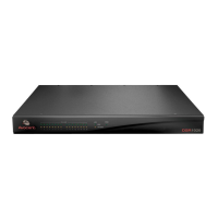
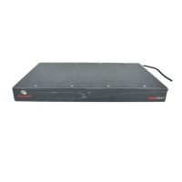
Figure 1.2 on page 3 illustrates and describes the DSR1021 switch.
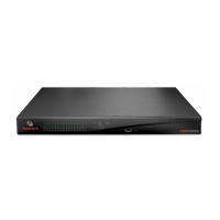
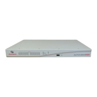
Figure 1.3 on page 4 illustrates and describes the DSR1022 switch.