10 DSR2035/8035 Switch Installer/User Guide
8. (Optional) To configure the DSR2035/8035 switch using the console menu interface, use the
second supplied ribbon cable and RJ-45 to DB9 (female) adaptor to connect a terminal or a PC
that is running terminal emulation software (such as HyperTerminal
®
) to the SETUP port on
the back panel of the DSR2035/8035 switch. The terminal should be set to 9600 bits per
second (bps), 8 bits, 1 stop bit, no parity and no flow control. Otherwise, proceed to the
next
step.
9. Power up each target device and then power up the DSR2035/8035 switch. After
approximately one minute, the switch completes initialization and displays the OSCAR
®
graphical user interface Free tag on the local port monitor.
10. Use the DSView 3 software to configure the switch. See the DSView Installer/User Guide for
detailed instructions.
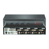
To connect a DSRIQ module to a server:
1. Attach the color-coded connectors of a DSRIQ module to the corresponding keyboard, monitor
and mouse ports on the server you will be connecting to this DSR2035/8035 switch.
2. Attach one end of the CAT 5 patch cable to the RJ-45 connector on the DSRIQ module.
Connect the other end of the CAT 5 patch cable to the desired port on the back of your
DSR2035/8035
switch.
Repeat this procedure for all servers you wish to attach.
NOTE: When connecting a Sun DSRIQ module, you must use a multi-sync monitor in the local port to
accommodate Sun computers that support both VGA and sync-on-green or composite sync.
To connect local virtual media:
Connect the virtual media to any one of the five USB ports on the DSR2035/8035 switch.
NOTE: For all virtual media sessions, you must use a USB2 or USB2L DSRIQ module.
To connect a DSRIQ module to a serial device:
1. Attach the DSRIQ-SRL module 9-pin serial connector to the serial port of the device to be
connected to your DSR2035/8035 switch.
2. Attach one end of the CAT 5 patch cable to the RJ-45 connector on the DSRIQ-SRL module.
Connect the other end of the CAT 5 patch cable to the desired port on the back of your
DSR2035/8035 switch.
NOTE: The DSRIQ-SRL module is a DCE device and only supports VT100 terminal emulation.
3. Connect the power supply to the power connector on your DSRIQ-SRL module. The cable
expander can be used to power up to four DSRIQ-SRL modules from a single power supply.
4. Connect the DSRIQ-SRL module power supply to a grounded AC wall outlet. Power up your
serial device. See
Appendix C on page 84 for more information on DSRIQ-SRL modules.