Do you have a question about the Awesomatix A800 and is the answer not in the manual?
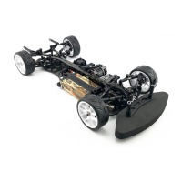
Congratulates the user on purchasing the A800 car.
Read manual, understand risks, and follow guidelines before assembly.
Precautions for small parts, sharp edges, rotating components, and safe operation.
Guidelines for safe usage, interference awareness, and battery handling.
Check parts, use online resources for build tips and images.
Lists necessary RC components like transmitter, receiver, motor, and battery.
Lists essential tools for assembly, including drivers, wrenches, and gauges.
Connects steering arms, blocks, and ball studs using specified screws and spacers.
Details all components required for completing Step 1.
Visual guide to the completed front and rear steering assembly.
Connects front axles, U-joint crosses, and universal bones with pins and rings.
Notes the option to use ST12 bushings or UB1 ball bearings.
Guidance on using a shaft collar for easier universal assembly.
Connects rear axles, U-joint crosses, and universal bones with pins and rings.
Notes the option to use ST12 bushings or UB1 ball bearings.
Guidance on using a screwdriver to unclamp rear axles.
Secures wheel hexes and lock rings to the axles.
Guidance on rear universal tightness and lock ring installation.
Connects suspension arms to the chassis bulkheads using screws.
Advice on screw tightening to ensure free ball joint action.
Introduces the D2.1 dampers, their adjustability, and factory oil.
Detailed instructions for rebuilding the dampers, including oil filling.
Notes that disassembly is performed by reversing the reassembly steps.
Connects damper holders, springs, rod guides, and screws to the damper body.
Method for inserting SPR02 into the vane slot, with a tip for grinding.
Caution about output shaft rotation limits and securing the damper.
Guidance on initial spring screw positions and avoiding overtightening.
Installs downstop collars and pivot balls onto the chassis.
Advises against fully tightening screws under AT21 balls at this stage.
Guidance on fitting ball cups and using spacers for setup.
Attaches ball studs to rear bulkheads and installs the motor mount.
Notes the option to install round weights for balance.
Installs satellite, bevel gears, pins, and washers into the differential housing.
Advises using thread lock and avoiding overtightening screws.
Combines differential case, bearings, output axle, and gears.
Instructions for filling the differential with the specified silicone oil.
Method for screwing the differential case onto the output axle.
Final assembly of the main differential housing parts.
Connects spool outdrives and pulleys to the spool axle.
Guidance on axle orientation, pulley alignment, and screw tightening.
Mounts bearing housings onto the drivetrain assembly.
Mounts front and rear shock holders onto the chassis.
Caution against overtightening SB3X8 screws during this step.
Installs the 20T alloy pulley and associated bearings.
Installs the front and rear drive belts onto the pulleys.
Notes that the AT67 ring should be positioned between the belts.
Installs the steering rack and bellcrank onto the chassis.
Connects front shock holders to the steering assembly.
Guidance on tightening shock holder screws with a 2mm hex driver.
Mounts the top deck, stiffeners, and related parts to the chassis.
Explains how screw count affects chassis flex.
Attaches ball studs and spacers to the rear suspension arms.
Attaches ball studs and spacers to the front suspension arms.
Attaches the shock rods to the suspension components.
Mounts sway bars and their associated holders to the chassis.
Mounts sway bars, stoppers, and joints, directing tips downwards.
Guidance on adjusting sway bar stopper placement for centering.
Emphasizes that sway bar holders are crucial for arm travel restriction.
Connects turnbuckles, ball joints, and rods for suspension links.
Notes on suspension settings and using a setup station.
Mounts battery holders and clamps to secure the battery.
Guidance on adjusting screws for battery placement and clearance.
Notes using round weights as alternative battery inner holders.
Installs the servo and central servo holder onto the chassis.
Advises on suitable servos and servo arm lengths.
Illustrates the correct neutral orientation of the servo arm.
Installs the bumper components at the front and rear of the chassis.
Attaches the spur gear and pinion, noting thickness requirements.
Advises on maximum thickness for spur and pinion gears.
Installs speed controller, receiver, battery, and wheels.
Notes using round weights for adjusting car weight and CG.
Details optional rear body holders, steering, and top stiffeners.
Description of the optional battery clamp set.
Instructions for assembling the optional flexible caster block.
Explains how to adjust camber and caster angles using rod lengths.
Provides a method for measuring caster and notes reactive caster possibility.
Covers upstop, downstop, roll center, wheelbase, and bump steer adjustments.
How to adjust damping and spring rates using A and B distances.
Adjusting spring preload with RHS screw to set ride height.
Illustrates two alternative arrangements for SRS and RHS screws.
Guide on using the DG1 Damper Gauge for shock measurements.
Graph showing suspension rate for SPR01 springs based on screw settings.
Graph showing suspension rate for SPR01S soft springs based on screw settings.
Specifies the overall drive train ratio as 1.9.
Chart detailing final drive ratios for 64dp gears.
Chart detailing final drive ratios for 48dp gears.
Fields for recording camber, caster, toe, ride height, and downstop settings.
Details for front/rear suspension, shock oil, spring, and rotor settings.
Sections for frame flex settings, tire brand, and wheel choices.
Areas for motor, servo, ESC, battery, receiver, and best lap time.
Detailed list of standard spare parts and their identifiers.
Detailed list of optional parts and their identifiers.
| Drive Type | 4WD |
|---|---|
| Scale | 1/10 |
| Suspension | Double Wishbone |
| Motor Type | Brushless |
| ESC | Not included |
| Battery Type | LiPo |
| Battery Voltage | 7.4V |