Do you have a question about the Axial SCX10 RAM Power Wagon and is the answer not in the manual?
Guidelines for choosing safe and appropriate locations for operating the R/C model.
Ensuring the model is properly inspected and all components are secure before operation.
Steps to follow after operating the R/C model, including power down and battery care.
Instructions on how to properly charge the vehicle's battery pack.
Step-by-step guide to turning on the transmitter and electronic speed controller.
Checklist for ensuring all pre-operation steps and component checks are completed.
Checklist for initial driving, system checks, and ongoing vehicle maintenance.
Steps to verify the radio system's operating range and functionality.
Details on essential checks for maintaining the R/C vehicle's performance and longevity.
Instructions for setting up and calibrating the AE-5 Electronic Speed Controller.
Technical specifications and status indicator meanings for the AE-5 ESC.
Overview of the AX-3 transmitter's controls, settings, and functions.
Procedures for binding the radio system and configuring the fail-safe function.
Guide for installing batteries into the AX-3 transmitter.
Information regarding the limited warranty for Axial products and claims procedures.
Policies for international customers regarding warranty and product support.
Contact information and process for obtaining repair services for Axial products.
Solutions for problems where the R/C vehicle does not move or respond.
Troubleshooting steps for loss of control or incorrect operation of the R/C model.
Reference diagram for axle, hub, and suspension linkage components.
Identification of transmission gear cover and associated mounting parts.
Diagrams for frame brace sets and various shock absorber parts.
Reference for radio box and battery tray mounting parts.
Identification of suspension linkage sets and driveshaft components.
Reference for wheel caps, tires, spur gears, and gear sets.
Diagrams for input shafts, outdrive shafts, and various gear components.
Reference for specific fasteners like pins, screws, and gaskets used in the drivetrain.
Identification of various hex socket and button head screws with different lengths.
Reference for bearings, e-clips, and specialized screw shafts and nuts.
Exploded diagram detailing the main chassis frame and suspension linkage assembly.
Exploded view of the transmission housing, gears, and drive axle components.
Diagram illustrating the assembly of suspension arms, shocks, and frame braces.
Exploded view showing various mounting points and components attached to the chassis.
Diagram detailing the assembly of the axle differential housing and wheel hubs.
Exploded view of shock absorber components and suspension linkage parts.
Diagram showing the assembly of wheel hubs, tires, and related hardware.
Exploded view of various drivetrain parts including gears, shafts, and differentials.
| Scale | 1/10 |
|---|---|
| Ground Clearance | 2.7 in (68 mm) |
| Drive | 4WD |
| Chassis | Steel C-channel |
| Battery | 7.2V NiMH or 2S LiPo (not included) |
| Suspension | 4-link |
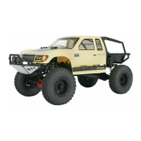
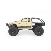
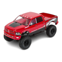
| Body | RAM Power Wagon |
| Width | 9 in (229 mm) |
| Radio | 2.4GHz |
| ESC | Waterproof (Included) |
| Servos | Tactic TSX45 metal gear servo |
| Shock Type | Oil-Filled |
| Drive System | Shaft driven |
| Wheelbase | 12.3 inches (312.4mm) |
| Weight | 4.5 lb (2 kg) |