AXIS 200+ Users Manual Section 2: Installing the AXIS 200+
13
Note:
❏ If the Adobe Acrobat Reader 3.0 is not installed on your system,
locate and run the appropriate installer from the
tools/Acrobat/ folder. Refer to the readme.txt file for full
path name details.
HTML Interface
You can access a Web browser interface to the contents of the AXIS
Online CD by clicking the HTML button from within the main
installation dialog. This interface allows Network Administrators to
distribute the CD contents over intranet networks by simply
broadcasting a URL reference.
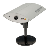
Stage 2. Identifying the Connectors and Indicators
Please read the following information to familiarize yourself with the
AXIS 200+, making particular note of where the connectors and
indicators are located. This information provide a useful reference
when performing the remaining stages of the installation.
Connectors
Auxiliary I/O
Connector
A Mini-DIN 8-pole external connector for auxiliary connection to the
AXIS 200+. The functionality of this connector is fully discussed in
Appendix D - The Auxiliary IO Port.
NetPower
Control Ethernet RS232 serialPower supplySnapshot Auxiliary I/O
Camera lens
Serial number
connector
10baseTindicator
button
indicatorLock ring CS ring
indicator