Do you have a question about the Axis A8004 and is the answer not in the manual?
Axis disclaims responsibility for product use and manual errors.
Axis policy on product improvement and specification changes.
Instructions on avoiding unauthorized equipment changes.
Product meets IT equipment safety standards.
Axis contact details and technical support resources.
Guidance on environmentally safe disposal and recycling.
Identifies junction box (1x) and screws (4x).
Diagrams for cutting an opening and connecting I/O cables.
Diagram showing the junction box being mounted.
Diagram showing cable routing to the junction box.
Diagram showing the junction box secured with screws.
Diagram showing cables connected to the device.
Diagram showing IP 66 rated I/O cables connected.
Diagram showing the device secured with screws.
Diagram showing the unit mounted onto the junction box.
Diagram showing the cover being attached with screws.
Diagram illustrating the final mounting action.
Diagram showing final securing of the unit with screws.
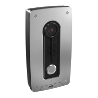
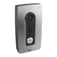
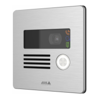
The AXIS A8004 Junction Box is an accessory designed to facilitate the installation and wiring of compatible Axis devices, particularly those requiring secure and weather-protected cable management. This junction box provides a robust enclosure for electrical connections, ensuring that the integrity of the system is maintained in various environmental conditions. Its primary function is to offer a clean and organized way to route and protect cables, making installations more professional and durable.
One of the key usage features of the AXIS A8004 Junction Box is its adaptability to different installation scenarios. The design includes multiple knock-out holes, allowing for flexible cable entry from various directions. This versatility is crucial for installers who need to adapt to specific site requirements, whether mounting on a wall, pole, or other surfaces. The junction box is designed to integrate seamlessly with Axis devices, providing a secure mounting point that also serves as a conduit for power and data cables. The internal layout is optimized to accommodate cable slack and connectors, preventing strain on the connections and ensuring a neat appearance. This is particularly important for outdoor installations where exposure to elements could otherwise compromise cable integrity.
The installation process for the AXIS A8004 Junction Box is straightforward, emphasizing ease of use while maintaining high standards of protection. The guide illustrates how to prepare the mounting surface, including marking and drilling holes for secure attachment. It specifies the required drill bit sizes and torque settings for screws, ensuring a stable and reliable installation. The inclusion of a template for marking drill points simplifies the process, reducing the likelihood of errors. Once the junction box is mounted, cables can be routed through the designated knock-out holes. The guide provides clear instructions on how to remove these knock-outs and how to properly seal the cable entries to maintain the enclosure's environmental rating. This attention to detail in cable management is vital for preventing water ingress and protecting internal components from dust and other contaminants.
Another significant aspect of the AXIS A8004 Junction Box's usage is its role in maintaining the overall aesthetic of an installation. By concealing cables and connections within the box, it contributes to a cleaner and more professional look, which is often a requirement in public or visible locations. The robust construction of the box also adds a layer of physical protection to the connections, deterring tampering and accidental damage. This makes it suitable for deployment in areas where security and durability are paramount. The junction box is designed to be compatible with various Axis camera models and other accessories, ensuring a cohesive and integrated system.
Maintenance features for the AXIS A8004 Junction Box are primarily focused on ensuring its long-term reliability and the protection it offers. The materials used in its construction are selected for their durability and resistance to environmental factors such as UV radiation, extreme temperatures, and corrosion. This minimizes the need for frequent replacement or repair of the box itself. Access to the internal connections is facilitated by a removable cover, which is secured with screws. This design allows for easy inspection, troubleshooting, or modification of wiring without having to dismount the entire box. When accessing the interior, it is important to follow the specified torque settings when re-securing the cover to ensure that the environmental seal is maintained.
Proper sealing of cable entries is a critical maintenance consideration. The installation guide emphasizes the importance of using appropriate cable glands or sealing solutions to prevent moisture and dust from entering the enclosure. Regular checks of these seals, especially in harsh environments, can help prevent long-term damage to the internal wiring and connected devices. Should any seals show signs of wear or damage, they should be replaced promptly to preserve the junction box's protective capabilities. The overall design of the AXIS A8004 Junction Box aims to be a "set and forget" component, requiring minimal ongoing maintenance once correctly installed. Its robust build and thoughtful design contribute to the longevity and reliability of the entire surveillance system it supports.
In summary, the AXIS A8004 Junction Box serves as an essential component for professional and secure installations of Axis devices. Its design prioritizes flexible cable management, environmental protection, and ease of installation, while its durable construction ensures minimal maintenance requirements over its operational lifespan.
| Resolution | 1280 x 720 (HD 720p) |
|---|---|
| Frame Rate | 30 fps |
| Network Protocols | IPv4, IPv6, HTTP, HTTPS, RTSP, RTP, UDP, TCP, IGMP, ICMP, DHCP, ARP, DNS, DynDNS, NTP, UPnP, Bonjour |
| Security | HTTPS encryption, IP address filtering, Password protection, User access log |
| Interfaces | 1 x RJ45 10/100 Mbps Ethernet (PoE), 1 x 3.5 mm audio input, 1 x 3.5 mm audio output |
| Network interface | 1 x RJ45 10/100 Mbps Ethernet (PoE) |
| Power | PoE (IEEE 802.3af) |
| Humidity | 10 - 100% RH (condensing) |
| Video Compression | H.264, MJPEG |