3
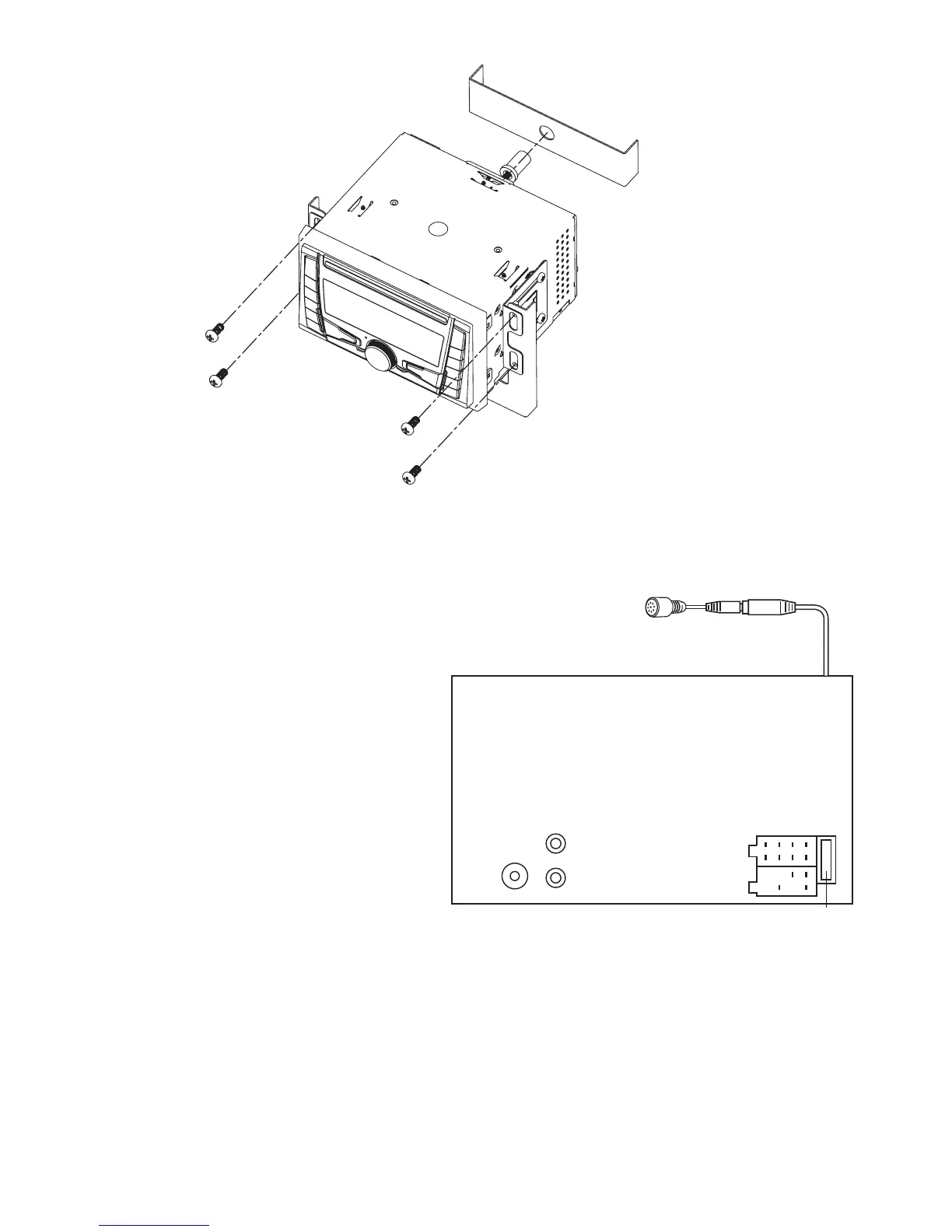
TO SUPPORT THE UNIT
WIRE CONNECTION
RCA Jack Line Out: White (left) Red (right)
CONNECTOR A
MEMORY +24V
AUTO ANTENNA OUTPUT
+24V (TO IGNITION KEY)
GROUND
Note: (connector A no. 7) must be connected WR
ignition FLUFXLW in order to avoid the car battery
being drained when the car will be not used for
a long period.
CONNECTOR B
1. REAR RIGHT SPEAKER (+)
2. REAR RIGHT SPEAKER (-)
3. FRONT RIGHT SPEAKER (+)
4. FRONT RIGHT SPEAKER (-)
5. FRONT LEFT SPEAKER (+)
6. FRONT LEFT SPEAKER (-)
7. REAR LEFT SPEAKER (+)
8. REAR LEFT SPEAKER (-)
Maintenance
FUSE REPLACEMENT
If the fuse blows, check the power connection and replace the fuse. If the fuse blows again after the replacement, there
may be an internal malfunction. In this case, consult your nearest repair centUH
Warning
Use the specified amperage fuse for each lead. Use of a higher amperage fuse may cause serious damageDQGYRLG
WKHZDUUDQW\
R(RED)
L(WHITE)
LINE OUT
ANTENNA
CONNECTOR
FUSE 10A
A
B
ISO CONNECTOR
8642
7531
84
75
CONNECT TO EXTERNAL
MICROPHONE