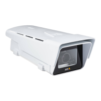
AXISP1425-LEMkIINetworkCamera
HardwareOverview
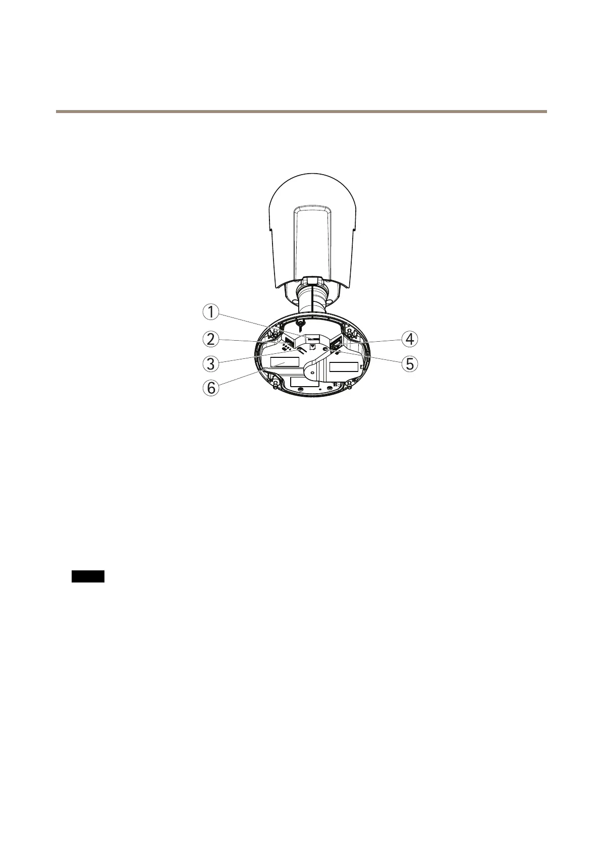
HardwareOverview
1
microSDcardslot
2
I/Oconnector
3
Controlbutton
4
Networkconnector
5
StatusLEDindicator
6
Partnumber(P/N)&Serialnumber(S/N)
ConnectorsandButtons
Fortechnicalspecications,seepage66.
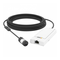
NetworkConnector
RJ45EthernetconnectorwithPoweroverEthernet(PoE).
NO NO
NO
TICE TICE
TICE
Theproductshallbeconnectedusingashieldednetworkcable(STP).Allcablesconnectingtheproducttothenetworkshall
beintendedfortheirspecicuse.Makesurethatthenetworkdevicesareinstalledinaccordancewiththemanufacturer’s
instructions.Forinformationaboutregulatoryrequirements,seeElectromagneticCompatibility(EMC)onpage2.
I/OConnector
Usewithexternaldevicesincombinationwith,forexample,tamperingalarms,motiondetection,eventtriggering,timelapserecording
andalarmnotications.Inadditiontothe0VDCreferencepointandpower(DCoutput),theI/Oconnectorprovidestheinterfaceto:
•Digitaloutput–ForconnectingexternaldevicessuchasrelaysandLEDs.Connecteddevicescanbeactivatedbythe
VAPIX®ApplicationProgrammingInterface,outputbuttonsontheLiveViewpageorbyanActionRule.Theoutputwill
showasactive(shownunderSystemOptions>Ports&Devices)ifthealarmdeviceisactivated.
•Digitalinput–Analarminputforconnectingdevicesthatcantogglebetweenanopenandclosedcircuit,forexample:
PIRs,door/windowcontacts,glassbreakdetectors,etc.Whenasignalisreceivedthestatechangesandtheinputbecomes
active(shownunderSystemOptions>Ports&Devices).
7