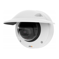
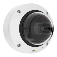
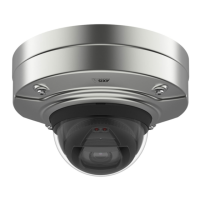
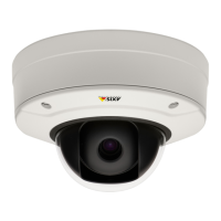
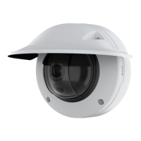
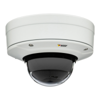
AXIS Q35 Series
Specifications
Function Pin Notes
Specications
DC ground
1
0 V DC
DC output
2
Can be used to power auxiliary equipment.
Note: This pin can only be used as power out.
12 V DC
Max load = 50 mA
Congurable
(Input or Output)
3–4
Digital input or Supervised input – Connect to pin 1 to activate, or
leave oating (unconnected) to deactivate. To use supervised input,
install end-of-line resistors. See connection diagram for information
about how to connect the resistors.
0 to max 30 V DC
Digital output – Connect to pin 1 to activate, or leave oating
(unconnected) to deactivate. If used with an inductive load, e.g., a
relay, connect a diode in parallel with the load, to protect against
voltage transients.
0 to max 30 V DC, open drain,
100 mA
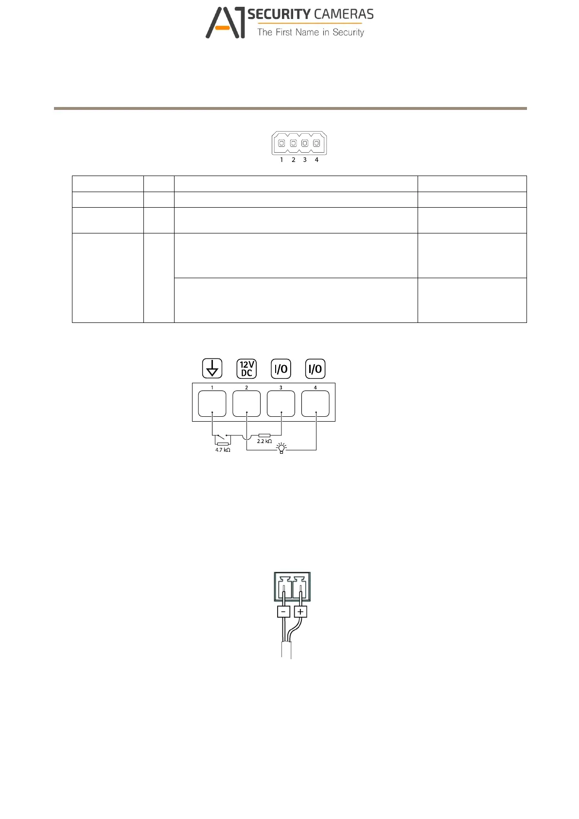
Example
1
DC ground
2
DC output 12 V, max 50 mA
3
I/O congured as supervised input
4
I/O congured as output
Power connector
2-pin terminal block for DC power input. Use a Safety Extra Low Voltage (SELV) compliant limited power source (LPS) with either
a rated output power limited to ≤100 W or a rated output current limited to ≤5 A.
19
Available from A1 Security Cameras
www.a1securitycameras.com email: sales@a1securitycameras.com
 Loading...