27
WARNING!! DISCONNECT THE MACHINE
FROM THE MAINS BEFORE CONTINUING!
Ascertain the orientation of the machine and move it to
its desired position in the workshop. Ensure that the
machine is positioned to allow sufficient clearance all
round to cater for the maximum length of timber you
wish to machine. The machine should be positioned on
a flat level surface. Manoeuvre the machine to the
chosen location making sure there is sufficient space all
round, then carefully lower the machine down.
Setting the Saw Blade at 90˚
Setting the Saw Blade at 45˚
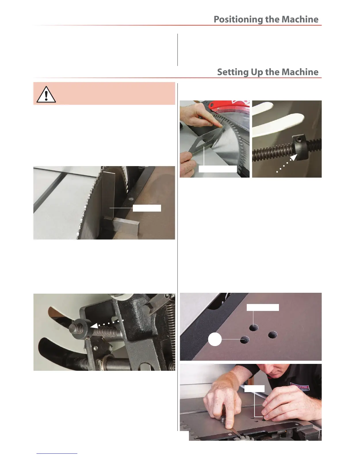
1. Remove the crown guard and place to one side, raise
the saw to it’s maximum height by turning the operating
wheel counterclockwise, place a 90˚ square up against
the saw blade and check the blade is 90˚ to the table, see
fig 87.
Fig 87
2. If the blade needs adjustment loosen the grub screws
on the 90˚stop collar on the saw assembly, see fig 88 and
adjust the collar in small increments until the bade is
perpendicular with the table. Nip up the collar to lock
the setting. Reset the pointer if required.
Fig 88
3. Set the angle of the saw to 45˚ degrees, place a mitre
square up against the blade and check it is 45˚ with the
table. If adjustment is required loosen the grub screws
on the 45˚stop collar on the saw assembly, see fig 89
adjust the collar in small increments until the bade is
perpendicular with the table. Nip up the collar to lock
the setting.
Fig 89
Setting Scoring Blade
90˚ Degrees
1. Lower the saw assembly with the rise and fall hand
wheel until the scoring saw is just below the table. You
will require a feeler gauge and Hex key.
2. Loosen the adjuster lock with a Hex key, adjust the
cap head screw (A), set the saw blade height (clockwise
to raise the blade and anti-clockwise to lower the blade),
until the scoring blade is level with the table. Recheck the
height of the scoring blade and adjust it above the table
to 1 or 2mm. Lock the scoring blade in position using the
adjuster lock, see fig 90-91-92.
Fig 90-91-92
Adjuster lock
A
Hex key
45˚ Mitre square
90˚ Square
 Loading...