– 6 – – 7 –
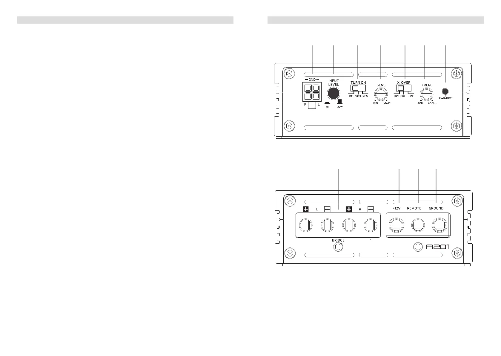
A201 CONNECTIONS + CONTROLS
1 SIGNAL INPUTS R / L
Low-level stereo RCA signal or high-level speaker signal input terminal for connection
to head-unit.
2 INPUT MODE SELECTION
Switch to select the proper input sensitivity range: RCA signal input = Low. Speaker
signal input = Hi.
3 AUTO-TURN-ON MODE
Slide switch to select the auto-turn-on function: REM by remote wire, VOX to switch on
by music signal or DC by DC offset signal of the head units integrated amplier.
4 INPUT SENSITIVITY CONTROL
Input gain potentiometer “SENS” to match the output voltage of the head unit to the
amplier’s input.
5 OPERATION MODE SWITCH
Slide switch to select the operation mode of the X-over of the amplier: Highpass
[HPF], Lowpass [LPF] or full [FULL] signal.
6 X-OVER FREQUENCY CONTROL
Control potentiometer to adjust the highpass or lowpass ltering frequency of the
amplier.
7 POWER LED
LED to show the operating status of the amplier by blue/red illumination. Blue is
normal working mode, red is protect mode of amplier.
8 SPEAKER OUTPUT TERMINAL
Output terminal to connect the speakers to the amplier in either stereo or bridged
mode.
9 “+12 V” POWER INPUT TERMINAL
Terminal to connect the amplier to the positive +12V pole of the car battery.
10 “REM” INPUT TERMINAL
Terminal to connect the amplier to the automatic (remote) turn-on / turn-off lead of the
head unit. By using the REM terminal, you need to switch the Auto-turn-On mode
3
to the “REM” position.
11 “GND” POWER INPUT TERMINAL
Terminal to connect the amplier to the chassis ground or negative pole of the car
battery.
A201 CONNECTIONS + CONTROLS
8 9 bl bm
41 2 5 6 73
 Loading...