– 4 – – 5 –
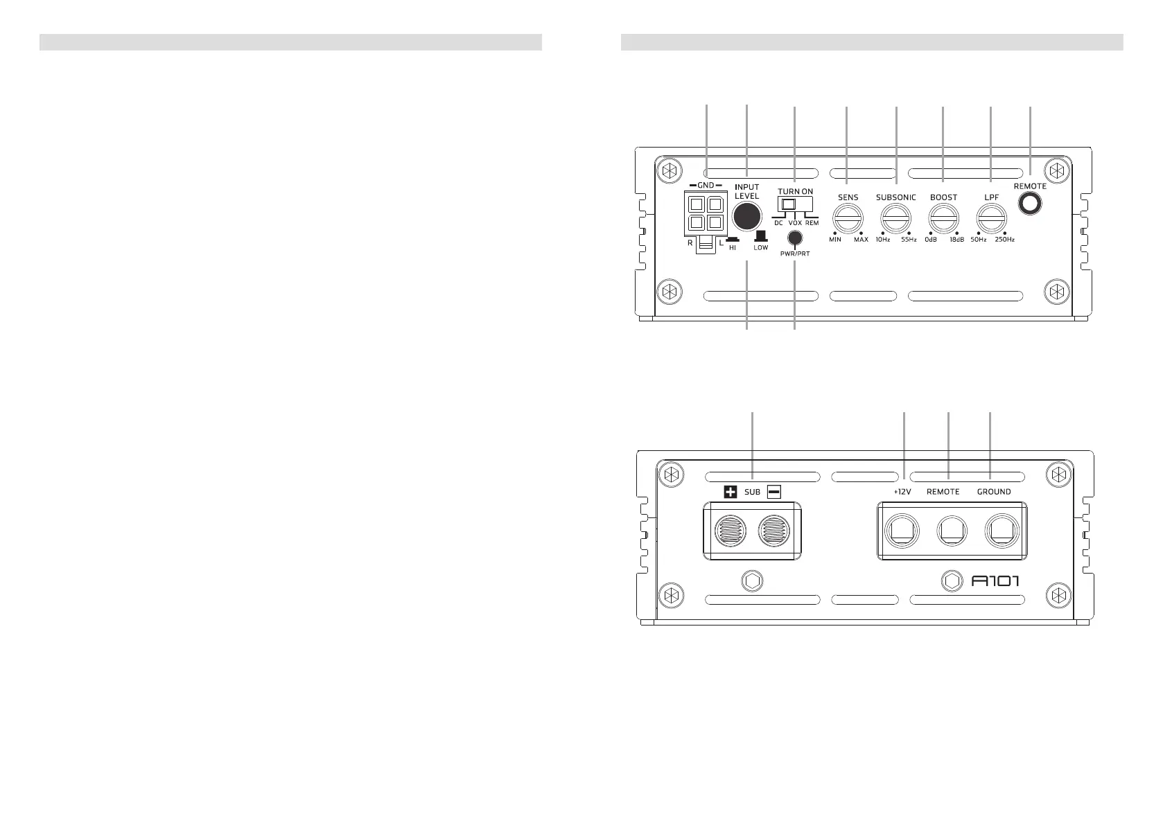
A101 CONNECTIONS + CONTROLS
1 SIGNAL INPUTS R / L
Low-level stereo RCA signal or high-level speaker signal input terminal for connection to
head-unit.
2 INPUT MODE SELECTION
Switch to select the proper input sensitivity range: RCA signal input = Low. Speaker
signal input = Hi.
3 AUTO-TURN-ON MODE
Slide switch to select the auto-turn-on function: REM by remote wire, VOX to switch on
by music signal or DC by DC offset signal of the head units integrated amplier.
4 INPUT SENSITIVITY CONTROL
Input gain potentiometer “SENS” to match the output voltage of the head unit to the
amplier’s input.
5 SUBSONIC HIGHPASS FREQUENCY CONTROL
Control potentiometer to adjust the subsonic highpass ltering frequency point of the
subwoofer output channel.
6 BASS BOOST 0dB to + 18dB
Turn clockwise to get up to + 18dB bass boost or counterclockwise for no boost with a
45 Hz center frequency of the amplied output signal.
7 LOWPASS FREQUENCY CONTROL
Control potentiometer to adjust the lowpass ltering frequency point of the subwoofer
output channel.
8 BASS LEVEL REMOTE CONTROL INPUT
Input terminal to connect the external bass level remote to the amplier.
9 INPUT MODE SELECTION
Switch to select the proper input sensitivity range: RCA signal input = Low. Speaker
signal input = Hi.
10 POWER LED
LED to show the operating status of the amplier by blue/red illumination. Blue is
normal working state, red is protect mode of amplier.
11 SPEAKER OUTPUT TERMINAL
Output terminal to connect the speakers to the amplier.
12 “+12 V” POWER INPUT TERMINAL
Terminal to connect the amplier to the positive +12V pole of the car battery.
13 “REM” INPUT TERMINAL
Terminal to connect the amplier to the automatic (remote) turn-on / turn-off lead of the
head unit. By using the REM terminal, you need to switch the Auto-turn-On mode
3
to
the “REM” position.
14 “GND” POWER INPUT TERMINAL
Terminal to connect the amplier to the chassis ground or negative pole of the car
battery.
A101 CONNECTIONS + CONTROLS
bm bn bo bp
1 2
3 4 5 6 7 8
bl9
 Loading...