– 10 – – 11 –
A601 CONNECTIONS + CONTROLS
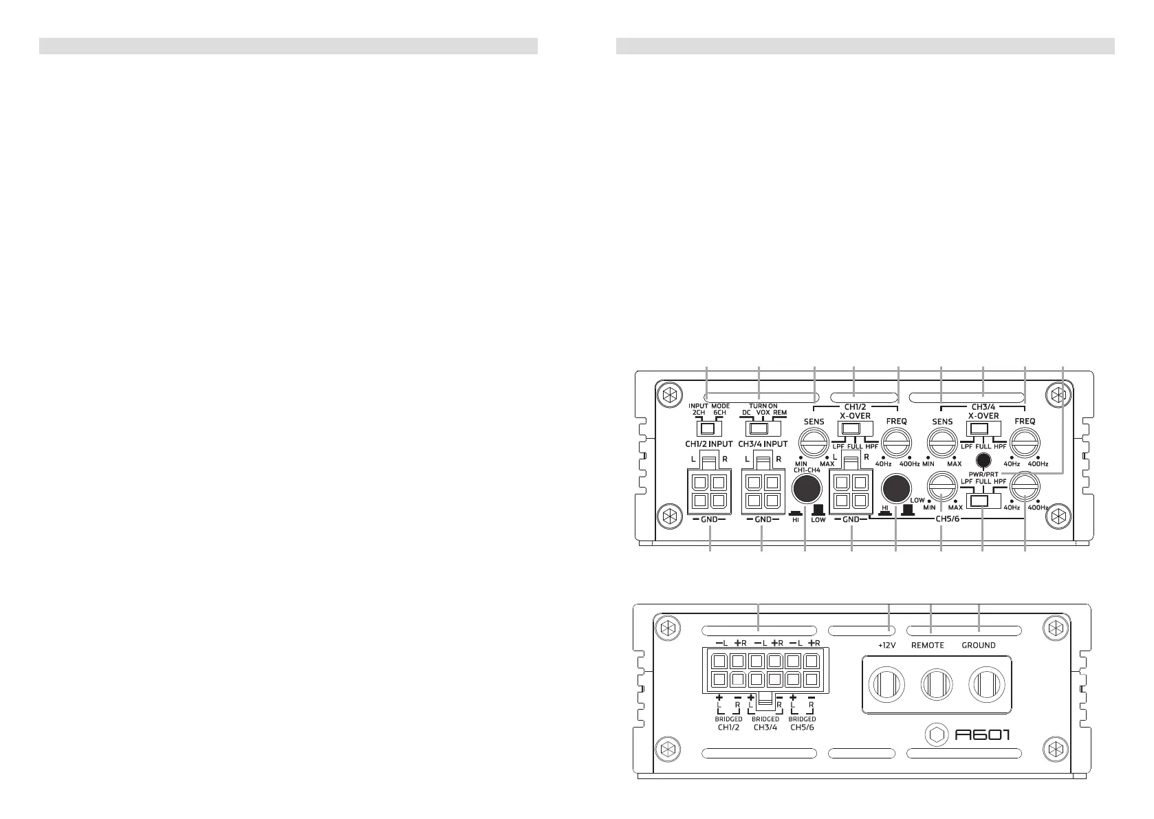
1 INPUT SIGNAL SELECTION
Slide switch to select the input signal for all channels. “2-CH” to use only CH1/CH2 input
terminal for all output channels. “6-CH” to give each output channel its corresponding
input channel.
2 AUTO-TURN-ON MODE
Slide switch to select the auto-turn-on function: REM by remote wire, VOX to switch on
by music signal or DC by DC offset signal of the head units integrated amplier.
3 INPUT SENSITIVITY CONTROL CH1/CH2
Input gain potentiometer “SENS” for channel CH1/CH2, to match the output voltage of
the head unit to the amplier’s input.
4 OPERATION MODE SWITCH CH1/CH2
Slide switch to select the operation mode of the X-over for section CH1/CH2 of the
amplier: Highpass [HPF], Lowpass [LPF] or full signal [FULL].
5 X-OVER FREQUENCY CONTROL CH1/CH2
Control potentiometer to adjust the highpass or lowpass ltering frequency for section
CH1/CH2 of the amplier.
6 INPUT SENSITIVITY CONTROL CH3/CH4
Input gain potentiometer “SENS” for channel CH3/CH4, to match the output voltage of
the head unit to the amplier’s input.
7 OPERATION MODE SWITCH CH3/CH4
Slide switch to select the operation mode of the X-over for section CH3/CH4 of the
amplier: Highpass [HPF], Lowpass [LPF] or full signal [FULL].
8 X-OVER FREQUENCY CONTROL CH3/CH4
Control potentiometer to adjust the highpass or lowpass ltering frequency for section
CH3/CH4 of the amplier.
9 POWER LED
LED to show the operating status of the amplier by blue/red illumination. Blue is normal
working state, red is protect mode of amplier.
10 SIGNAL INPUTS FRONT CH1/CH2
Low-level stereo RCA signal or high-level speaker signal input terminal for connection to
head-unit.
11 SIGNAL INPUTS FRONT CH3/CH4
Low-level stereo RCA signal or high-level speaker signal input terminal for connection to
head-unit.
12 INPUT MODE SELECTION CH1/CH2/CH3/CH4
Switch to select the proper input sensitivity range: RCA signal input = Low. Speaker
signal input = Hi.
13 SIGNAL INPUTS FRONT CH5/CH6
Low-level stereo RCA signal or high-level speaker signal input terminal for connection to
head-unit.
14 INPUT MODE SELECTION CH5/CH6
Switch to select the proper input sensitivity range: RCA signal input = Low. Speaker
signal input = Hi.
15 INPUT SENSITIVITY CONTROL CH5/CH6
Input gain potentiometer “SENS” for channel CH5/CH6, to match the output voltage of
the head unit to the amplier’s input.
A601 CONNECTIONS + CONTROLS
16 OPERATION MODE SWITCH CH5/CH6
Slide switch to select the operation mode of the X-over for section CH5/CH6 of the
amplier: Highpass [HPF], Lowpass [LPF] or full signal [FULL].
17 X-OVER FREQUENCY CONTROL CH5/CH6
Control potentiometer to adjust the highpass or lowpass ltering frequency for section
CH5/CH6 of the amplier.
18 SPEAKER OUTPUT TERMINAL
Output terminal to connect the speakers to the amplier in either stereo or bridged
mode.
19 “+12 V” POWER INPUT TERMINAL
Terminal to connect the amplier to the positive +12V pole of the car battery.
20 “REM” INPUT TERMINAL
Terminal to connect the amplier to the automatic (remote) turn-on / turn-off lead of the
head unit. You must switch
2
to “REM” when using the remote wire input terminal.
21 “GND” POWER INPUT TERMINAL
Terminal to connect the amplier to the chassis ground or negative pole of the car
battery.
bt
bu cl cm
2 3 4 5 6 7 81
bl bm bn bo bp bsbrbq
9
 Loading...