Introduction
vii
1. Attachment of feedback lever
In order to minimize the risk of damage to the feedback lever
while it is carried or transported, and to minimize the pack-
aging as well, the feedback lever is detached from the body of
the device when it is packed. As a result, the feedback lever
must be attached to the body of the device prior to installa-
tion of the device.
The length of the feedback lever can if necessary be adjusted
by attaching the extension lever between the feedback lever
and the body of the device. Adjustment of the feedback lever
length is determined based on the form of the actuator.
If the actuator type is speci-
fied when ordering, and the
extension lever is included:
Attach the extension lever to the
body of the device, and then attach
the feedback lever.
If the actuator type is speci-
fied when ordering, and the
extension lever is not in-
cluded:
The extension lever is not neces-
sary. Attach the feedback lever
directly to the body of the device.
If the actuator type is not
specified when ordering:
The extension lever will be in-
cluded. Refer to the table below to
determine, based on the actuator
with which the device is equipped,
whether or not the extension lever
is necessary.
Manufacturer Extension Lever Actuator Type Code
Azbil
Corporation
Yes
VP5, 6, 7 Y1
SLOP560, 1000, 1000X Y2
SLOP1500, 1500X Y3
DAP560, 1000, 1000X Y4
DAP1500, 1500X Y5
(SLOP type and DAP type are limited to products with stroke of
100 mm or less)
When connecting an actuator other than those in the table,
connect the device and the actuator, and then, via manual
operation, move the actuator slowly and ensure that the feed-
back lever does not interfere with a full stroke of the actuator.
If the feedback lever alone cannot cover a full stroke, attach
the extension lever to it.
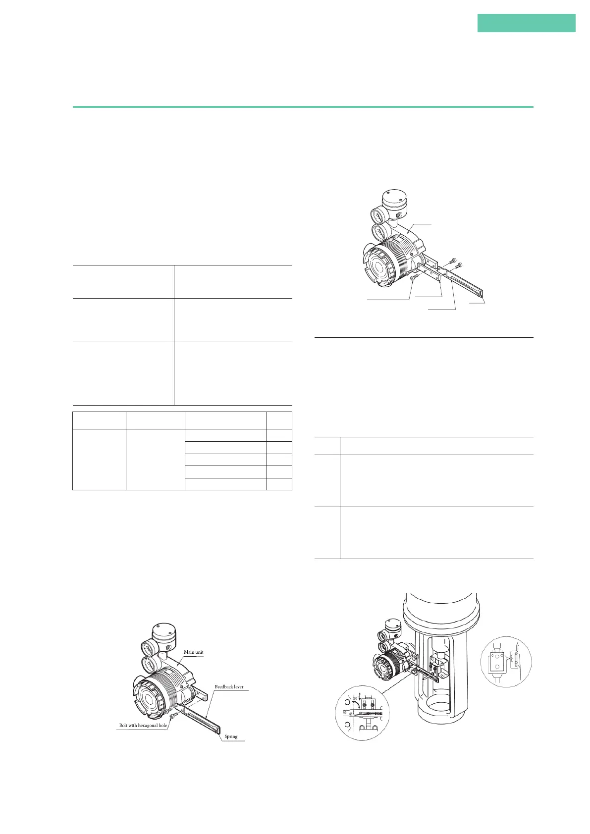
Attach the feedback lever securely, working from the front of
the device, using the two included hexagon socket head bolts.
Attachment of Feedback Lever
Combination of model AVP300/301/302 (integral type) and double-acting linear cylinder
actuator
Attach the extension lever securely, working from the front of
the device, using the two included hexagon socket head bolts.
Then, in the same way, attach the feedback lever securely,
working from the back of the device. (The feedback lever can
be attached from the front as well.)
Main unit
Bolt with hexagonal hole
Spring
Feedback lever
Extension lever
Attachment of Extension Lever and Feedback Lever
2. Attachment and installation
[1] Attachment to the actuator
Attach to the actuator with a mounting plate that is appropri-
ate for the actuator.
[2] Adjustment of attachment positions
Procedure for adjustment of attachment positions
Step Procedure
1 Using for example the manual handle of the actuator
or manual operation via the external pressure regulator
with filter, set the position to 50%. (With a double-acting
actuator, manual operation cannot be performed using the
A/M switch.)
2 Adjust the actuator such that the feedback lever reaches a
90° angle to the device's central vertical axis. Depending on
the actuator being used, adjustment may be performed by
moving the device, or it may be performed by moving the
pin.
Note: The accuracy specifications can be satisfied by making
the attachment angle 90° ±2°.
Adjustment of Attachment Positions
 Loading...

