vi
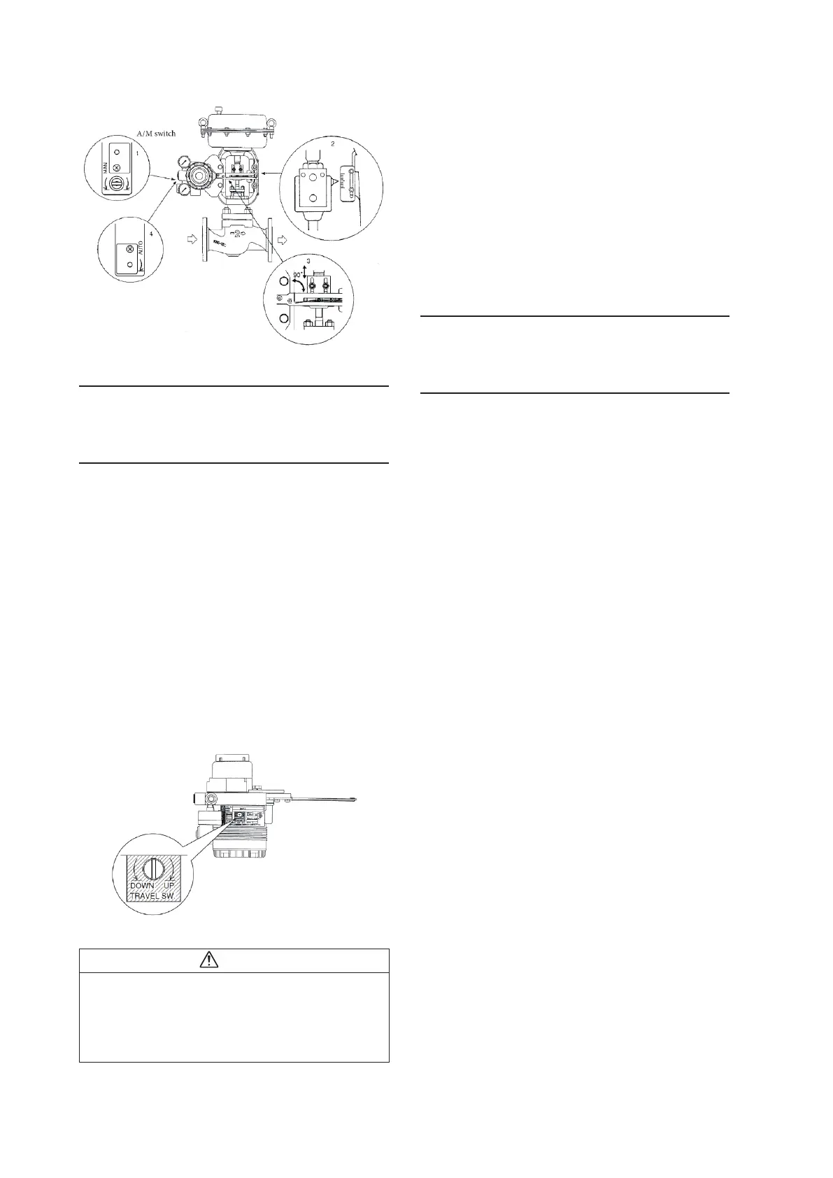
Adjustment of Attachment Positions
3. Air piping and electric wiring connection
Connect the air piping and electrical wiring.
For details, see 2.2, “Installation Method,” in this document.
4. Auto-setup
(1) Set the input signal to 18 ±1mA.
(2) Using a flat-blade screwdriver, turn the external zero/
span adjustment switch in the upper part of the case 90°
in the UP direction (the DOWN direction for Azbil Cor-
poration's VR and RSA actuators for VFR type control
valves), and hold that position for three seconds.
Note: For reverse close (when the valve's fully closed posi-
tion is on top), set the valve action to reverse close before-
hand. See 4.4.3, “Valve system”
(3) The valve will automatically start to move, and will stop
in about 3 to 4 minutes.
(4) When it stops, adjust it to a position that fits the input
signal.
(5) After that, check whether it has been adjusted correctly.
• Auto-setup can be performed with CommStaff as well.
Warning
When auto-setup is performed, the valve moves from fully
closed to fully open, so there is a danger of, for example,
getting your hand caught or affecting the process.
Before performing auto-setup, move away from the valve,
and confirm that the process is safe.
Note: When closing the
valve of the single-acting
type device with the lever
in the upward direction,
first set it to reverse close.
If performing auto-setup
External zero/span adjustment switch
UP direction: direct type
DOWN direction:
VFR type
Check the span point and perform span adjustment.
(1) Set the input signal to the span point (URV). (Zero ad-
justment can be performed if the input signal is adjusted
to the zero point, and span adjustment can be performed
if the input signal is adjusted to the span point.)
(2) Using a flat-blade screwdriver, turn the external zero
span adjustment switch on the upper part of the case UP
(clockwise) to cause the valve to move such that the feed-
back lever rises upward, or turn it DOWN (counterclock-
wise) to cause the valve to move such that the feedback
lever drops downward.
5. Operation confirmation
Vary the input signal, and check the zero point and span
point.
6. If suitable adjustment was not accomplished
[1] If auto-setup does not operate
• Check whether the input signal is 18 mA ± 1 mA.
• Check whether the A/M switch is set to automatic. If it is
set to manual, switch it to auto. See 5.2, “A/M Switch,” in
this document for information on operating procedures.
• Check the duty value of the electro-pneumatic module.
Regarding the confirmation method, see “EPM (electro-
pneumatic module) operation confirmation procedure” on
page 3-9 in this document.
• Check whether the electronics module (terminal block) is
installed correctly in the case on the body of the device.
[2] If hunting occurs
• Using the setup device, either change the actuator size
(Param) or individually set the valve position control PID.
Regarding the configuration method, see 4.4.4, “Control
configuration,” below.
[3] If the zero point floats or span adjustment cannot be
performed
Referring to Table 3-1, “Integral type setting,” in 3.1, “Auto-
setup,” in this document, check whether valve action is
configured correctly. If not, it will be necessary to change the
valve action (the direct/reverse setting). Referring to 4.4.3,
“Valve system,” in this document, configure the valve action
correctly.
[4] If linearity characteristic is poor
• Check whether, when the attachment position of the feed-
back lever is the 50% opening position, it is attached hori-
zontally. If not, refer to 2.2, “Installation Method,” in this
document and correctly attach the feedback lever.
• Check the flow rate characteristics data. If equal%, quick
open, or the like has been specified, and these are funda-
mentally unnecessary, refer to 4.4.6, “Flow Type,” in this
document and change this setting to linear.
 Loading...

