Introduction
v
1. Attachment of feedback lever
In order to minimize the risk of damage to the feedback lever
while it is carried or transported, and to minimize the pack-
aging as well, the feedback lever is detached from the body of
the device when it is packed. As a result, the feedback lever
must be attached to the body of the device prior to installa-
tion of the device.
The length of the feedback lever can if necessary be adjusted
by attaching the extension lever between the feedback lever
and the body of the device. Adjustment of the feedback lever
length is determined based on the form of the actuator.
If the actuator type is specified
when ordering, and the
extension lever is included:
Attach the extension lever to the
body of the device, and then attach
the feedback lever.
If the actuator type is specified
when ordering, and the
extension lever is not included:
The extension lever is not necessary.
Attach the feedback lever directly to
the body of the device.
If the actuator type is not
specified when ordering:
The extension lever will be
included. Refer to the table below
to determine, based on the actuator
with which the device is equipped,
whether or not the extension lever
is necessary.
Manufacturer Extension Lever Actuator Type Code
Azbil
Corporation
No
PSA1, 2, PSK1 YS
HA1 YA
HA2, 3 YT
HK1 YK
VA1 to 3 YQ
Ye s
PSA3, 4 YQ
PSA6 YL
HA4 YN
PSA7 Y8
VA4 to 6 YL
RSA1 YF
RSA2 YU
VR1 YV
VR2, 3 YR
VR3H Y6
GOM83S, 84S, 103S YG
GOM124S YM
Motoyama
No #240, #280, #330 TA, TD
Ye s
#400, #500S, #500L TB, TE
#650S, #650L TC, TF
Masoneilan
No #11, #13 MA, MB
Ye s #15, #18 MC, MF
Nihon Koso
No #270, #320 TA, TD
Ye s #400, #500 TB, TE
When connecting an actuator other than those in the table,
connect the device and the actuator, and then switch to
manual mode and move the actuator slowly and ensure that
the feedback lever does not interfere with the full stroke of
the actuator.
If the feedback lever alone cannot cover a full stroke, attach
the extension lever to it.
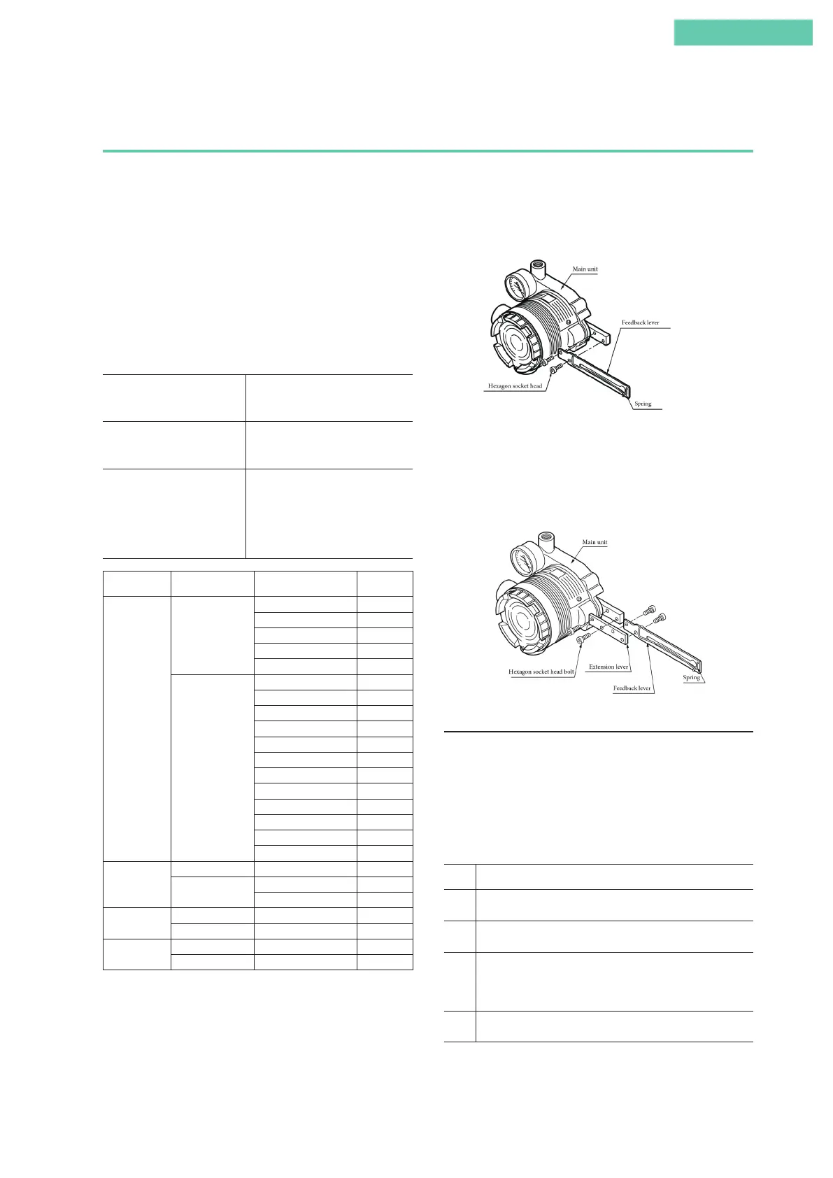
Attach the feedback lever securely, working from the front of
the device, using the two included hexagon socket head bolts.
Attachment of Feedback Lever
Attach the extension lever securely, working from the front of
the device, using the two included hexagon socket head bolts.
Then, in the same way, attach the feedback lever securely,
working from the back of the device. (The feedback lever can
be attached from the front as well.)
Attachment of Extension Lever and Feedback Lever
2. Attachment and installation
[1] Attachment to the actuator
Attach to the actuator with a mounting plate that is appropri-
ate for the actuator.
[2] Adjustment of attachment positions
Procedure for adjustment of attachment positions
Step Procedure
1 Set the A/M switch to manual operation.
(See 5.2, “A/M Switch.”)
2 Supply air, and adjust the actuator air pressure such that the
actuator stem reaches the travel midpoint.
3 Adjust the actuator such that the feedback lever reaches a
90° angle to the device's central vertical axis. Depending on
the actuator being used, adjustment may be performed by
moving the device, or it may be performed by moving a pin.
4 Set the A/M switch to automatic operation.
(See 5.2, “A/M Switch.”)
Note: The accuracy specifications can be satisfied by making
the attachment angle 90° ±2°.
Combination of model AVP300/301/302 (integral type) and single-acting linear
diaphragm actuator