1-2
1.1 System Configuration
This device is a smart valve positioner that can be connected to a 4 to 20 mA signal line
from the output of a controller. Since all adjustments can be performed electrically, any
desired relationship can be set between the input signal and the position of the control
valve. Split range and other special settings are also easy to specify. In addition, by using
a four-line connection, the device can transmit the control valve position to the host
monitoring system as either a 4 to 20 mA analog signal or as a DE digital signal.* (Only
models AVP301 and AVP201 have travel transmission.)
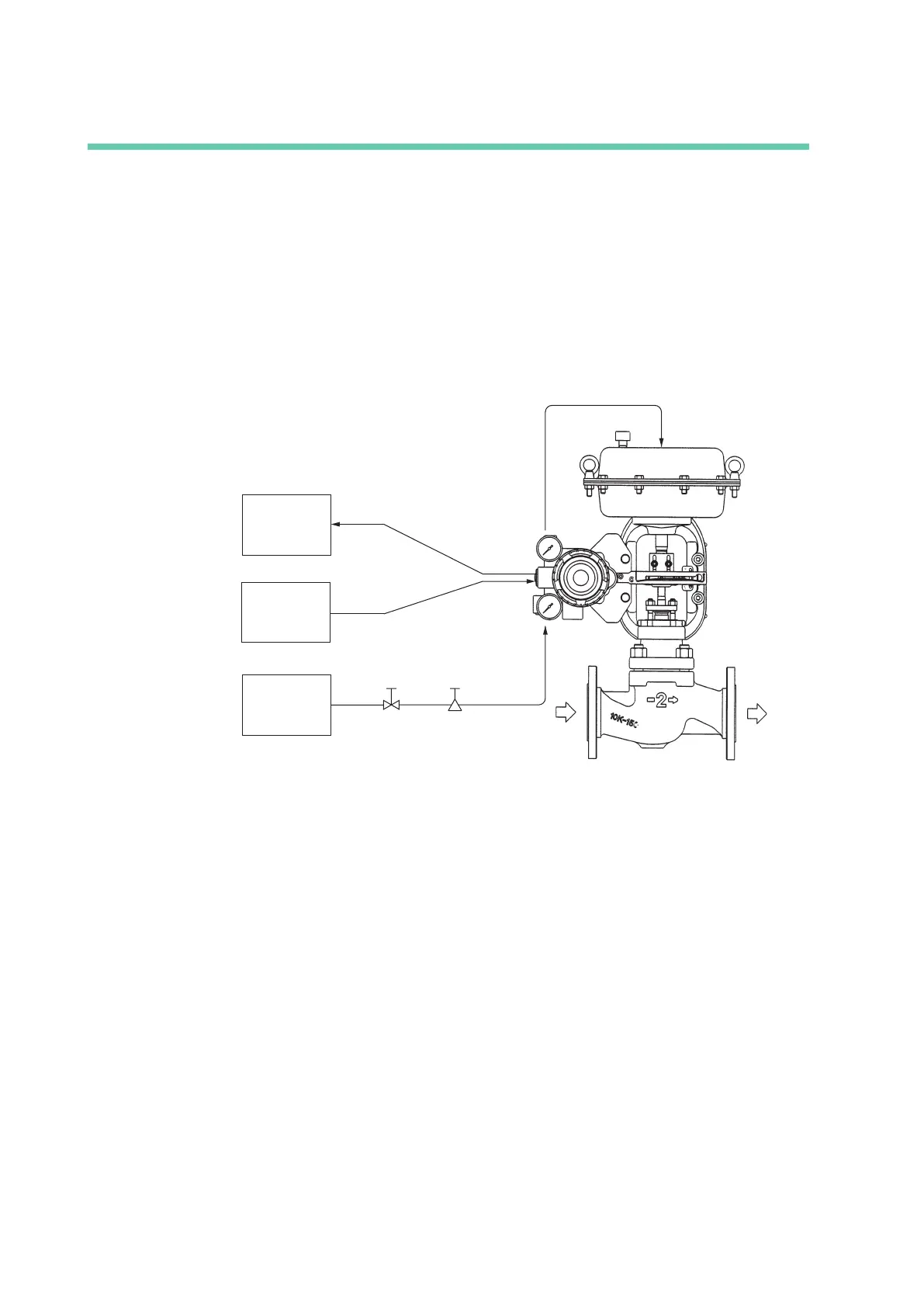
An overview of the control valve control system used by this device is shown below.
Host monitoring
system
Air supply
system
Host controller
4-20 mA DC analog signal
4-20 mA DC analog signal or DE
digital signal (model AVP301/201)
Shuto
valve
Regulator
with lter
Supply air
Actuator air
Control valve
Process uid
Figure 1-1. Control System Overview Diagram
*DE and the DE protocol are registered trademarks of Honeywell International, Inc. in the United
States.
 Loading...
