2-7
Chapter 2: Installation
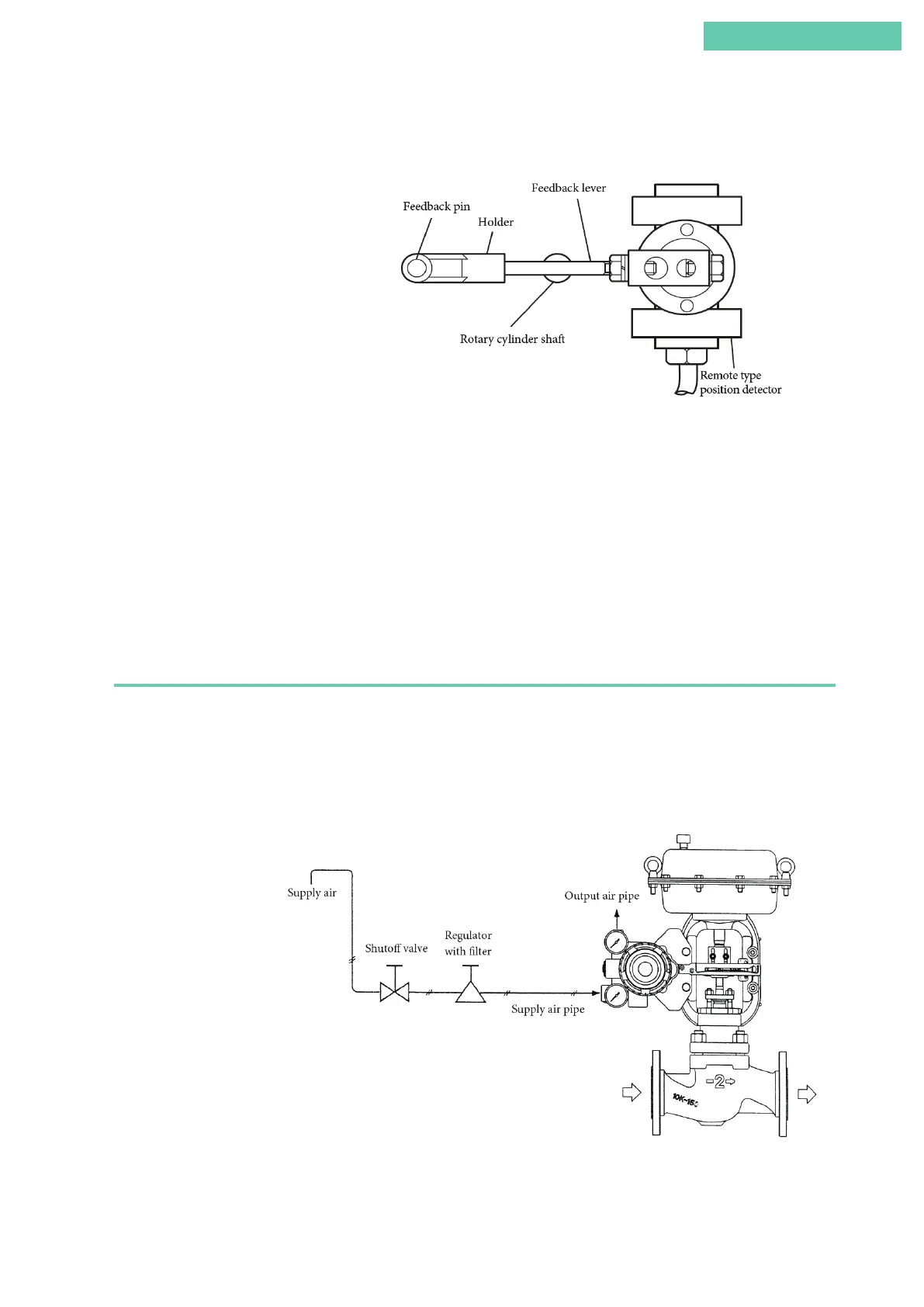
(5) If attaching a rotary cylinder, attach it so that the rotary cylinder shaft comes be-
tween the feedback pin and the device.
Figure 2-5. Connection of Remote Type and Rotary Cylinder’s Feedback Pin and Feedback Lever
■ Rear maintenance space
The device has a flapper nozzle mechanism at the rear of the main unit. The device is
designed such that, when cleaning the flapper, the flapper nozzle mechanism can be ac-
cessed by removing the pilot relay cover at the back of the main unit.
Before mounting the positioner on the actuator, consider a design for the mounting
bracket and feedback mechanism that leaves sufficient maintenance space for the pilot
relay cover, which is secured by three screws, to be removed, and for the work described
above to be carried out.
2.2.2 Air piping connection
The method for supplying air to drive the actuator of this device will now be described.
■ Air supply system
In order to ensure safe long-term use of this device, the supply air must be clean and
dry. A typical air supply system is shown in the diagram below.
Figure 2-6. Air Supply System
 Loading...
