1-5
Chapter 1: Control System Structure
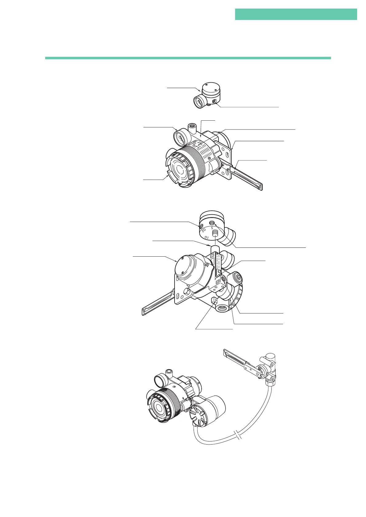
1.3 Description of Device Structure and Functions
The structure of the body of the device is shown below.
Pilot relay cover
Supply air connection
Output air connection
A/M switch
Supply air pressure gauge
External ground
terminal
Reversing relay supply air connection
Output air connection (OUT2)
Mounting plate (optional)
Feedback lever
Body
Terminal
box cover
Output air
pressure gauge
External zero/span adjustment switch
Output air connection (OUT1)
Reversing relay
Position detector
Positioner body
Figure 1-5-1. Body Structure (Front)
Figure 1-5-2. Body Structure (Rear)
Figure 1-5-3. 200 Series
 Loading...
